Interviews are opportunities to demonstrate your expertise, and this guide is here to help you shine. Explore the essential Hole Making and Layout Planning interview questions that employers frequently ask, paired with strategies for crafting responses that set you apart from the competition.
Questions Asked in Hole Making and Layout Planning Interview
Q 1. Explain the different types of hole-making processes.
Hole-making processes encompass a range of techniques used to create holes in various materials. The choice of process depends heavily on factors like material properties, hole size, precision requirements, and production volume. Here are some key types:
- Drilling: This is the most common method, using a rotating drill bit to cut a hole. It’s versatile and suitable for various materials and hole sizes.
- Reaming: Reaming follows drilling to enlarge a pre-existing hole to a precise diameter. It improves surface finish and accuracy.
- Boring: Boring creates larger, more accurate holes than drilling. It uses a single-point cutting tool, often in a lathe or boring mill.
- Punching: A high-speed process using a punch press to create holes in sheet metal. Ideal for high-volume production of simple holes.
- Laser Cutting: Uses a high-powered laser to melt and vaporize material, creating precise holes in various materials, including thin metals and plastics.
- EDM (Electrical Discharge Machining): A non-traditional process employing electrical sparks to erode material, creating complex shapes and precise holes in hard-to-machine materials.
Each process has its strengths and limitations, and selecting the right one is crucial for efficiency and quality.
Q 2. Describe the various types of drills and their applications.
Drill bits come in a wide variety of types, each designed for specific applications. The selection depends on material, hole size, and desired surface finish.
- Twist Drills: The most common type, featuring helical flutes that remove chips effectively. Available in high-speed steel (HSS), carbide, and cobalt variations for different materials.
- Step Drills: Create multiple diameters in a single pass, saving time in certain applications. Useful for pilot holes and countersinking.
- Counterbore Drills: Create a larger diameter hole at a specific depth, often used for bolt heads or screw seating.
- Countersink Drills: Chamfer the edges of a hole to accommodate countersunk screws, creating a flush surface.
- Core Drills: Used for large-diameter holes and often have a pilot hole to guide the cutter.
- Annular Cutters: Remove a core of material, producing cleaner holes with less material removal compared to standard drills. Suitable for thick materials.
Choosing the right drill ensures efficient cutting, prevents breakage, and achieves the desired hole quality.
Q 3. What are the key considerations for selecting a drilling machine for a specific task?
Selecting the right drilling machine requires considering several key factors:
- Material to be drilled: Hard materials necessitate a robust machine with sufficient power and speed control.
- Hole size and accuracy: Precise holes require a machine with a precise spindle and appropriate tooling.
- Production volume: High-volume production benefits from automated drilling machines or CNC machining centers.
- Machine capacity: The machine’s capacity should accommodate the workpiece dimensions.
- Budget and available space: Costs and workspace limitations influence machine selection.
- Safety features: Emergency stops, guards, and other safety features are critical for operator safety.
For example, drilling numerous small holes in a thin sheet metal part would require a different machine than creating a large-diameter hole in a thick steel block. Careful consideration of these factors ensures efficient and safe operation.
Q 4. How do you ensure accurate hole placement using layout techniques?
Accurate hole placement is crucial for assembly and functionality. Several layout techniques ensure precision:
- Scribing and measuring: Using precision measuring tools and scribers to mark hole centers directly on the workpiece. This method is suitable for simple layouts.
- Templates: Pre-made templates with pre-drilled holes act as guides, offering accuracy for repetitive tasks.
- Jigs and fixtures: Specialized holding devices that precisely position the workpiece and guide the drill bit. Essential for high-accuracy and repeatable drilling.
- Coordinate measuring machines (CMMs): Used for inspecting and verifying hole locations in complex parts.
- CNC machining: A highly accurate method using computer-controlled machines to drill holes based on programmed coordinates.
For instance, when creating multiple holes for a circuit board, a drill jig ensures precise spacing and alignment, preventing misalignments that could affect functionality.
Q 5. Explain the importance of proper tooling in hole making.
Proper tooling is paramount in hole making. Using the incorrect tools leads to inaccurate holes, damaged workpieces, and potentially dangerous situations.
- Sharpness: Dull tools create oversized holes, poor surface finish, and increased cutting forces, potentially causing workpiece damage or tool breakage. Regular sharpening or replacement is crucial.
- Material compatibility: The drill bit material must be appropriate for the workpiece material. Using the wrong type will lead to inefficient cutting or tool failure.
- Size and type: Selecting the right drill bit size and type (twist drill, counterbore, etc.) is essential for achieving the desired hole characteristics.
- Proper clamping: Securely clamping the drill bit in the chuck prevents slippage and ensures accurate hole location.
Imagine attempting to drill through hardened steel with a standard HSS drill bit. The bit would likely break, resulting in wasted time, materials, and potentially injury.
Q 6. Describe your experience with different hole-making techniques (drilling, reaming, boring).
My experience spans a wide range of hole-making techniques. I’ve extensively used drilling for various applications, from simple pilot holes to intricate patterns in various materials. I’m proficient in selecting appropriate drill bits, speeds, and feeds for optimal results. I’ve also worked extensively with reaming, specifically using hand reamers and machine reamers to achieve precise hole diameters and high-quality surface finishes. This is crucial for applications requiring close tolerances and smooth surfaces.
Furthermore, I have significant experience in boring operations, particularly in lathe and milling machine environments. I’m comfortable using boring bars and cutters to create large, precise holes in demanding applications like engine blocks or aerospace components, focusing on minimizing chatter and ensuring dimensional accuracy.
Q 7. How do you calculate the required drill size for a specific application?
Calculating the required drill size depends on the application and the type of fastener being used. Here’s a common approach:
- For through holes with fasteners: The drill size should be slightly smaller than the fastener’s shank diameter. This allows for a snug fit and prevents the fastener from being too loose. The exact amount smaller depends on the material and the fastener type.
- For clearance holes: The drill size is typically slightly larger than the fastener’s diameter to allow for easy insertion and free movement.
- For tapped holes: The drill size is determined by the tap drill chart, providing the recommended drill size for achieving the correct thread depth and preventing stripping.
For example, if I’m using a 1/4-inch diameter screw, I might use a 7/32-inch drill bit for a through hole or a slightly larger bit for a clearance hole. Consulting a tap drill chart is necessary for precise hole size calculation when creating tapped holes.
Q 8. What are the common causes of inaccurate holes and how do you prevent them?
Inaccurate holes are a common problem in manufacturing, stemming from several sources. Think of it like baking a cake – if your measurements are off, the final product won’t be right. Similarly, in hole making, even small errors can have significant consequences.
- Dull Drill Bits: A dull bit can cause wandering, oversized holes, and excessive heat buildup, potentially damaging the workpiece. Imagine trying to dig a hole with a blunt shovel – it’s tough and inefficient.
- Improper Clamping: If the workpiece isn’t securely clamped, it can move during drilling, resulting in inaccurate hole placement. This is like trying to draw a perfect circle while the paper is shifting under your hand.
- Incorrect Drill Press Alignment: Misalignment of the drill bit with the workpiece will result in an off-center hole. This requires careful setup and attention to detail, like ensuring the center punch mark is precisely aligned.
- Excessive Feed Rate or Speed: Pushing the bit too hard or spinning it too fast can lead to inaccurate holes, broken bits, and workpiece damage. This is like trying to hammer a nail in too quickly – you risk bending it.
- Material Variations: Variations in the hardness or composition of the workpiece can affect drilling accuracy. Some materials are simply more challenging to drill through accurately than others.
Prevention involves:
- Regularly sharpening drill bits.
- Using appropriate clamping techniques to secure workpieces.
- Carefully aligning the drill bit with the center punch mark before drilling.
- Following recommended feed and speed guidelines for the specific material and bit.
- Using appropriate drill bits designed for the specific material being drilled.
Q 9. Explain your experience with different types of drill bits (twist drills, step drills, etc.).
I have extensive experience with various drill bits, each suited for different applications. It’s like having a toolbox full of specialized tools – each has its strengths and weaknesses.
- Twist Drills: These are the workhorses of hole making, versatile for a wide range of materials and hole sizes. Their helical flutes efficiently remove material and create clean holes. I frequently use them for general-purpose drilling.
- Step Drills: These bits have multiple cutting diameters, allowing for quick creation of holes with varying sizes in one operation. They are especially efficient for creating pilot holes followed by larger holes without repositioning the bit. I use them when time is critical and multiple holes of different diameters are needed in the same location.
- Brad Point Drills: These bits feature a sharp point for accurate starting and preventing wandering. The spurs ensure an accurate placement of the hole, especially in thinner materials. These are my go-to for precise work where starting hole accuracy is paramount.
- Countersink Bits: These are used to create a conical recess around a hole, typically before inserting a screw or rivet. They provide a clean, flush surface for fasteners. I frequently use these when finishing parts for a professional look.
My experience includes selecting the appropriate bit based on the material, hole size, depth, and required precision. This selection is crucial for maximizing efficiency and accuracy.
Q 10. How do you determine the appropriate feed and speed for drilling?
Determining the correct feed and speed is crucial for efficient and accurate drilling. It’s a balance – too slow and you waste time, too fast and you risk damaging the bit and workpiece. Think of it like cooking – you need the right heat and time for the best results.
Factors to consider:
- Material: Harder materials require slower speeds and lighter feeds. Softer materials allow for higher speeds and feeds.
- Drill Bit Diameter: Larger bits generally need lower speeds and feeds to avoid excessive heat and stress.
- Drill Bit Material: High-speed steel (HSS) bits can handle higher speeds than other types.
I typically use machinists’ handbooks or manufacturer’s recommendations as a starting point. I then adjust based on the sound and feel of the drilling operation. Excessive heat or chattering indicates the need for adjustment. There are online calculators and software programs that can assist in determining optimal feed and speed values based on numerous input parameters. Experience and fine tuning are key.
Q 11. What safety precautions do you take when operating drilling machines?
Safety is paramount in any machining operation, and drilling is no exception. I always adhere to strict safety protocols to protect myself and others.
- Eye Protection: Always wear safety glasses or a face shield to protect against flying debris.
- Hearing Protection: Drilling machines can be noisy; earplugs or earmuffs are necessary.
- Proper Clothing: Avoid loose clothing or jewelry that could get caught in the machine.
- Secure Workpiece: Ensure the workpiece is securely clamped to prevent movement during drilling.
- Machine Maintenance: Regularly inspect the machine for any damage or wear and tear.
- Emergency Stop: Know the location and operation of the emergency stop button.
- Machine Guards: Always use appropriate machine guards to minimize the risk of accidents.
Before starting any drilling operation, I conduct a thorough risk assessment, ensuring all safety precautions are in place. Safety isn’t just a checklist; it’s a mindset.
Q 12. How do you inspect the quality of a drilled hole?
Inspecting the quality of a drilled hole is essential to ensure it meets specifications. It’s like checking your cake for even baking and perfect texture.
My inspection typically involves:
- Visual Inspection: Checking for burrs, cracks, or other surface imperfections around the hole.
- Diameter Measurement: Using calipers or a micrometer to verify the hole diameter is within tolerance.
- Straightness Check: Ensuring the hole is straight and not tapered or misaligned.
- Depth Measurement: Verifying the hole depth matches the requirements.
- Surface Finish Inspection: Assessing the surface finish of the hole for smoothness or roughness requirements.
Depending on the application, more sophisticated inspection methods might be used, such as coordinate measuring machine (CMM) inspection for critical applications requiring exceptional accuracy. Documentation is crucial for maintaining traceability and quality control.
Q 13. Describe your experience with CAD/CAM software for hole making.
I have extensive experience using CAD/CAM software for hole making, which significantly improves efficiency and accuracy. It’s like having a detailed blueprint and precise instructions for creating holes.
I’m proficient in software such as Mastercam and Fusion 360. These programs allow me to:
- Design and Model Parts: Create accurate 3D models of parts, including precise hole locations and sizes.
- Generate Toolpaths: Automatically generate optimal toolpaths for drilling, ensuring efficient material removal and accuracy.
- Simulate Machining: Simulate the machining process virtually to identify potential problems or collisions before actual machining takes place.
- Optimize Processes: Optimize machining parameters such as feed and speed to minimize machining time and improve surface finish.
Using CAD/CAM significantly reduces the risk of errors associated with manual programming or layout, leading to higher quality and consistency in the final product. It’s an indispensable tool in modern manufacturing.
Q 14. Explain your understanding of tolerance and its relevance in hole making.
Tolerance in hole making refers to the permissible variation in the hole’s size and position. It’s the acceptable range of error, like allowing for a small difference in cake height.
Understanding tolerance is critical because:
- Interchangeability: It ensures that parts made with acceptable tolerance can be assembled without issues.
- Functionality: Tolerance limits affect how a part functions, such as a hole’s fit with a shaft.
- Cost: Tighter tolerances (smaller acceptable range of variation) require more precise manufacturing techniques, increasing costs.
Tolerance is specified using various standards such as ISO and ANSI. Understanding these standards and their implications is essential for ensuring the quality and functionality of a product. For example, a +0.01/-0.00 mm tolerance on a hole diameter means the hole can be 0.01mm larger or perfectly 0mm smaller than the nominal size.
Q 15. How do you handle complex layout requirements for multiple holes?
Handling complex layout requirements for multiple holes involves a systematic approach. It starts with a thorough understanding of the design specifications, including hole sizes, locations, tolerances, and any specific features like countersinking or counterboring. I typically utilize Computer-Aided Design (CAD) software to create a detailed drawing or model, which allows for precise placement of holes and verification against design requirements. For complex layouts, I might divide the process into smaller, more manageable sections or employ advanced techniques like coordinate measuring machines (CMMs) for verification. One example would be a complex engine block where hundreds of precisely located holes are required. Instead of manually marking each hole, I’d use a CAD program to generate a drill template or utilize a CNC machining center for automated drilling.
For particularly intricate designs, I rely on advanced software tools capable of generating NC (Numerical Control) code. This code directly drives CNC machines for precise and automated hole making, ensuring consistent accuracy across multiple parts. Think of it like a detailed recipe for the drilling machine, eliminating the possibility of human error in complex layouts. This also minimizes the risk of costly rework or scrapped parts.
Career Expert Tips:
- Ace those interviews! Prepare effectively by reviewing the Top 50 Most Common Interview Questions on ResumeGemini.
- Navigate your job search with confidence! Explore a wide range of Career Tips on ResumeGemini. Learn about common challenges and recommendations to overcome them.
- Craft the perfect resume! Master the Art of Resume Writing with ResumeGemini’s guide. Showcase your unique qualifications and achievements effectively.
- Don’t miss out on holiday savings! Build your dream resume with ResumeGemini’s ATS optimized templates.
Q 16. How do you ensure consistency in hole making across multiple parts?
Consistency in hole making is paramount and hinges on several factors. Firstly, it requires using properly calibrated and maintained drilling machines. Regular calibration ensures the machine operates within specified tolerances. Secondly, consistent tooling is crucial. This means employing drills with the correct diameter and geometry, as well as using appropriate cutting speeds and feeds tailored to the material being processed. For example, using a worn drill bit can lead to inconsistent hole sizes and potentially damage the part. Thirdly, the use of jigs and fixtures is vital, especially for high-volume production. These ensure repeatability by precisely guiding the drill bit to the correct location on every part. Finally, regularly inspecting the parts and checking dimensions with appropriate measuring tools verifies the consistency and flags potential issues early on.
Imagine mass-producing a circuit board. Inconsistent holes would mean components wouldn’t fit correctly, leading to malfunctioning products. Therefore, meticulously maintaining equipment, using standardized procedures, and implementing quality checks are non-negotiable to ensure hole-making consistency.
Q 17. What are the common problems encountered in hole making and how do you troubleshoot them?
Common problems in hole making include drill bit breakage, inaccurate hole placement, and hole surface imperfections. Drill bit breakage often results from using dull or improperly sized bits, excessive cutting pressure, or improper clamping of the workpiece. Inaccurate hole placement can stem from poorly designed jigs, operator error, or machine miscalibration. Finally, surface imperfections, such as burrs or excessive heat discoloration, are often caused by incorrect cutting parameters like speed and feed, or the use of inappropriate lubricants.
Troubleshooting involves a systematic approach. For instance, if a drill bit breaks, I’d check its sharpness, the correct speed and feed settings for the material, and the workpiece clamping. If holes are misaligned, I’d inspect the jig for damage or misalignment, check the machine’s calibration, and review the operator’s technique. Surface imperfections are usually addressed by adjusting cutting parameters, using appropriate lubricants, and considering a different drill bit material or geometry.
Q 18. How do you maintain drilling machines and associated tooling?
Maintaining drilling machines and tooling is essential for consistent performance and long-term durability. This involves regular cleaning and lubrication of moving parts to minimize friction and wear. I also regularly inspect the machine for any signs of damage or misalignment, addressing them promptly. Drill bits are inspected for sharpness and wear, replaced when necessary. Specific maintenance procedures are documented and followed, often including frequency and type of lubricant to use. Calibration checks and adjustments are performed according to the manufacturer’s specifications. This is similar to maintaining a car – regular servicing prevents major breakdowns and extends the machine’s lifespan. Proper maintenance not only ensures precision but also enhances safety and prevents unexpected downtime.
Q 19. Describe your experience working with different materials (steel, aluminum, plastics).
My experience encompasses working with various materials like steel, aluminum, and plastics. Each material requires a tailored approach to hole making. Steel, being relatively hard and strong, requires robust drill bits and careful selection of cutting speeds and feeds to prevent excessive wear and heat generation. Aluminum, being softer and more ductile, is easier to machine but can be prone to work hardening. Appropriate speeds and feeds are necessary to avoid this. Plastics, on the other hand, require specialized drill bits to prevent chipping or melting and careful selection of cutting speeds and feeds. Different types of steel even require different approaches, for example high-speed steel is tougher than mild steel.
For instance, when drilling through stainless steel, I always use a lubricant to reduce friction and prevent the drill bit from overheating. With aluminum, I might use a slightly lower speed and heavier feed to avoid work hardening. For plastics, I employ sharp drill bits and maintain cool cutting conditions to reduce the risk of melting or burring.
Q 20. How do you calculate the cutting parameters for different materials?
Calculating cutting parameters depends heavily on the material being drilled and the type of drill bit. The cutting speed (measured in surface feet per minute or SFM) and feed rate (measured in inches per revolution or IPR) directly influence the overall quality and efficiency of the hole-making process. These parameters are typically determined by consulting manufacturer’s recommendations and material property tables. Software and online calculators can assist in calculating optimal cutting parameters. The cutting speed must be reduced for harder materials, and the feed rate must be adjusted to account for the material’s machinability.
For example, drilling a harder material like hardened steel will require a lower cutting speed to prevent the bit from overheating and dulling prematurely. In contrast, a softer material like aluminum may allow for a faster cutting speed. The feed rate is adjusted in tandem with the cutting speed, as too high a feed can cause excessive chip load, while too low a feed can result in a slow machining rate. The correct combination of these parameters helps to extend the life of the drill bit and ensure a clean, accurate hole.
Q 21. Explain your experience with various types of drilling jigs and fixtures.
My experience includes using various drilling jigs and fixtures, from simple bush jigs for single holes to complex multi-axis fixtures for precise location of many holes. Simple jigs consist of a guide bush and a base plate to precisely guide the drill bit. More complex fixtures involve multiple guide bushings, clamping mechanisms, and indexing systems to handle multiple parts and holes simultaneously. These are frequently utilized in high-volume production to maintain consistent accuracy and efficiency. The choice of jig or fixture depends on the complexity of the part and the required accuracy and repeatability.
For example, when drilling multiple holes on a circuit board, a multi-axis CNC fixture might be used to locate and secure the circuit board, allowing precise drilling of all holes in one setup. Alternatively, a simple drill jig with multiple bushings would be sufficient for drilling holes in a small workpiece with fewer holes. Proper jig design ensures consistent hole alignment, reducing errors and increasing the efficiency of the manufacturing process.
Q 22. How do you deal with broken drill bits during operation?
Dealing with a broken drill bit is a common occurrence, but proper handling prevents further damage and ensures safety. First, I always ensure the machine is completely powered down and the bit is secured. Attempting to remove a broken bit while the machine is running is extremely dangerous.
The removal method depends on the type of break. If the shank is still intact, I can usually use a drill bit extractor – essentially a reverse-threaded bit designed to grip and remove the broken piece. For more stubborn breaks, or those close to the surface, I might need to use a hammer and chisel carefully, working to avoid damaging the surrounding material. In some cases, particularly with very hard materials or precision work, specialized tools like ultrasonic or EDM (Electrical Discharge Machining) methods might be necessary for removal.
Prevention is key. Selecting the correct drill bit for the material and application, using appropriate speeds and feeds, and regularly inspecting bits for wear and tear are crucial steps to minimize breakage.
Q 23. What are the different types of layout tools and instruments you are familiar with?
Layout tools and instruments are essential for accurate and efficient hole placement. My familiarity includes:
- Scribers: Used for marking lines and points on the workpiece.
- Dividers: For accurately transferring measurements and marking off equal distances.
- Combination Squares: Versatile tools providing a square, level, and protractor in one.
- Marking Gauges: Used for marking consistent depths or distances from an edge.
- Surface Plates and Straight Edges: Providing reference surfaces for accurate layouts.
- Dial Indicators: Used for precise measurements of runout and surface irregularities.
- Digital Calipers and Micrometers (detailed in the next answer): For highly precise measurements.
- Templates and Jigs: These are custom-made or pre-fabricated tools for repetitive layouts, significantly increasing efficiency and consistency.
The selection of tools depends entirely on the complexity of the layout, material properties and the required precision.
Q 24. Describe your experience with precision measurement tools (calipers, micrometers).
I have extensive experience using calipers and micrometers for precision measurement in hole making. Calipers provide quick and relatively accurate measurements, useful for determining the overall dimensions of a workpiece or checking the diameter of a hole after drilling. I routinely use both Vernier and digital calipers. Micrometers offer significantly higher precision, allowing for thousandths-of-an-inch (or even ten-thousandths) accuracy, essential for ensuring holes are within very tight tolerances, critical in applications like aerospace or medical device manufacturing.
For example, when machining a part requiring a hole with a tolerance of ±0.005”, I would use a micrometer to meticulously check the diameter of the hole after drilling to ensure it falls within the specified range. Similarly, I utilize calipers frequently for taking quick measurements during the layout phase to ensure accurate spacing between multiple holes. Proper care and calibration of these tools are critical for maintaining accuracy and extending their lifespan. I always ensure both are properly calibrated before and after each use using certified gauge blocks or other master standards.
Q 25. Explain your understanding of surface finish requirements in hole making.
Surface finish requirements in hole making are crucial. They directly impact the function and performance of the component. A rough surface finish might lead to increased friction, wear, or leakage in applications like hydraulic systems or fluid transfer. Conversely, a very smooth finish is often needed for a precise fit or to minimize wear in critical moving parts.
Surface finish is typically specified using parameters like Ra (average roughness) or Rz (maximum peak-to-valley height), often expressed in micrometers or microinches. The required surface finish dictates the choice of drilling methods and post-processing techniques. For example, a highly polished hole might necessitate reaming or honing after drilling, while a less demanding application might only need basic deburring. Understanding the specific application requirements and translating those into appropriate machining parameters and post-processing methods is fundamental.
Q 26. How do you interpret engineering drawings and specifications related to hole making?
Interpreting engineering drawings and specifications related to hole making is a fundamental skill. I meticulously examine drawings to identify all relevant information, such as:
- Hole Diameter and Tolerance: This dictates the drill bit size and the acceptable range of variation.
- Hole Location: Precise coordinates, often given in relation to datum points, are crucial for accurate layout.
- Hole Depth: The required depth is essential for drilling operations.
- Hole Type: This includes through-holes, blind holes, counterbores, countersinks, etc. Each type requires a different drilling technique.
- Surface Finish Requirements: As discussed earlier, this influences the choice of drilling method and post-processing.
- Material Specification: This helps in selecting appropriate drill bits and speeds.
Any discrepancies or ambiguities are always clarified with the design engineer to avoid costly mistakes. I utilize specialized software when dealing with complex drawings or large batches to ensure consistent and accurate interpretation and hole placement.
Q 27. Describe a time you had to solve a challenging problem related to hole making or layout planning.
During a project involving the manufacture of a high-precision injection molding tool, we encountered a challenge with aligning a series of very small, deep holes precisely. The initial layout process, using standard methods, resulted in unacceptable variations in hole positions, exceeding the tolerances specified by the customer.
To resolve this, I implemented a multi-stage process. First, we employed a high-precision CNC milling machine to create pilot holes with extremely tight tolerances. Then, I designed and fabricated a custom jig that precisely guided the drill bit to ensure perfect alignment during the subsequent drilling of the deep holes. This methodology eliminated much of the human error involved in manual layout and significantly improved consistency and accuracy. The project was successfully completed with all holes meeting the stringent specifications.
Q 28. What are your preferred methods for ensuring precise hole alignment?
Ensuring precise hole alignment is paramount. My preferred methods depend on the application, but generally involve a combination of techniques:
- Precise Layout: Using appropriate measuring tools and techniques, as discussed previously, to mark the hole locations accurately.
- Jig and Fixture Use: Employing custom-designed jigs and fixtures to guide the drill bit and ensure repeatability for multiple holes. This is especially crucial for mass production.
- Pilot Holes: Drilling small pilot holes first to guide larger drills. This increases accuracy and reduces the risk of wandering drill bits.
- CNC Machining: For high-precision and complex layouts, CNC machining offers unparalleled accuracy and repeatability.
- Coordinate Measuring Machine (CMM) Inspection: Post-machining inspection with a CMM confirms that hole positions meet the required specifications. This provides valuable feedback for continuous improvement.
The best method often involves a combination of these techniques to achieve the necessary level of precision.
Key Topics to Learn for Hole Making and Layout Planning Interview
- Hole Making Techniques: Understanding various drilling methods (e.g., twist drilling, reaming, boring), their applications, and limitations. Consider factors like material properties and desired hole tolerances.
- Layout Planning Fundamentals: Mastering blueprint reading, interpreting technical drawings, and translating design specifications into practical shop floor procedures. This includes understanding dimensioning and tolerancing.
- Tool Selection and Maintenance: Knowing the appropriate tools for different hole making tasks and understanding proper tool maintenance to ensure accuracy and longevity. This includes safety procedures related to tool usage.
- Material Considerations: Understanding the impact of material properties (hardness, ductility, etc.) on hole making processes and selecting appropriate techniques for different materials. This involves knowledge of common materials used in your industry.
- Jig and Fixture Design (if applicable): Knowledge of designing and using jigs and fixtures to ensure accuracy and repeatability in hole making processes. This might include understanding clamping mechanisms and alignment principles.
- Quality Control and Inspection: Understanding methods for inspecting hole quality (e.g., diameter, depth, surface finish) and identifying potential sources of error. This includes familiarity with relevant measuring instruments.
- Safety Procedures: Demonstrating a thorough understanding of all safety protocols and best practices related to hole making and layout planning. This should include personal protective equipment (PPE) and emergency procedures.
- Problem-Solving and Troubleshooting: Ability to diagnose and resolve issues that may arise during the hole making and layout process, including understanding root cause analysis techniques.
Next Steps
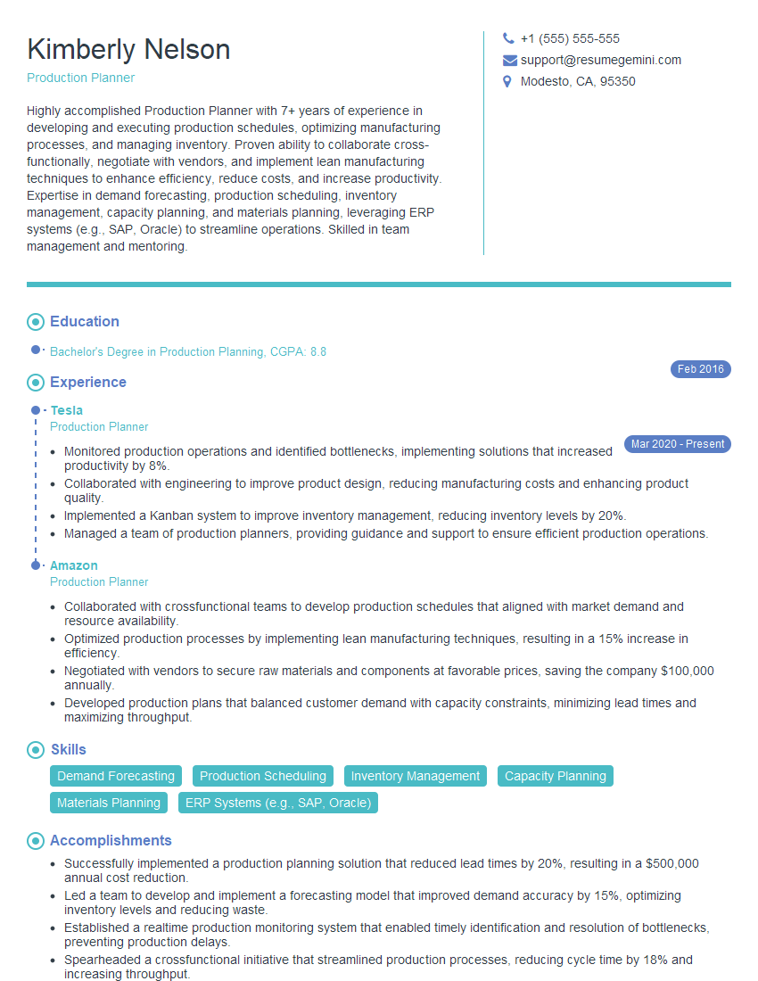
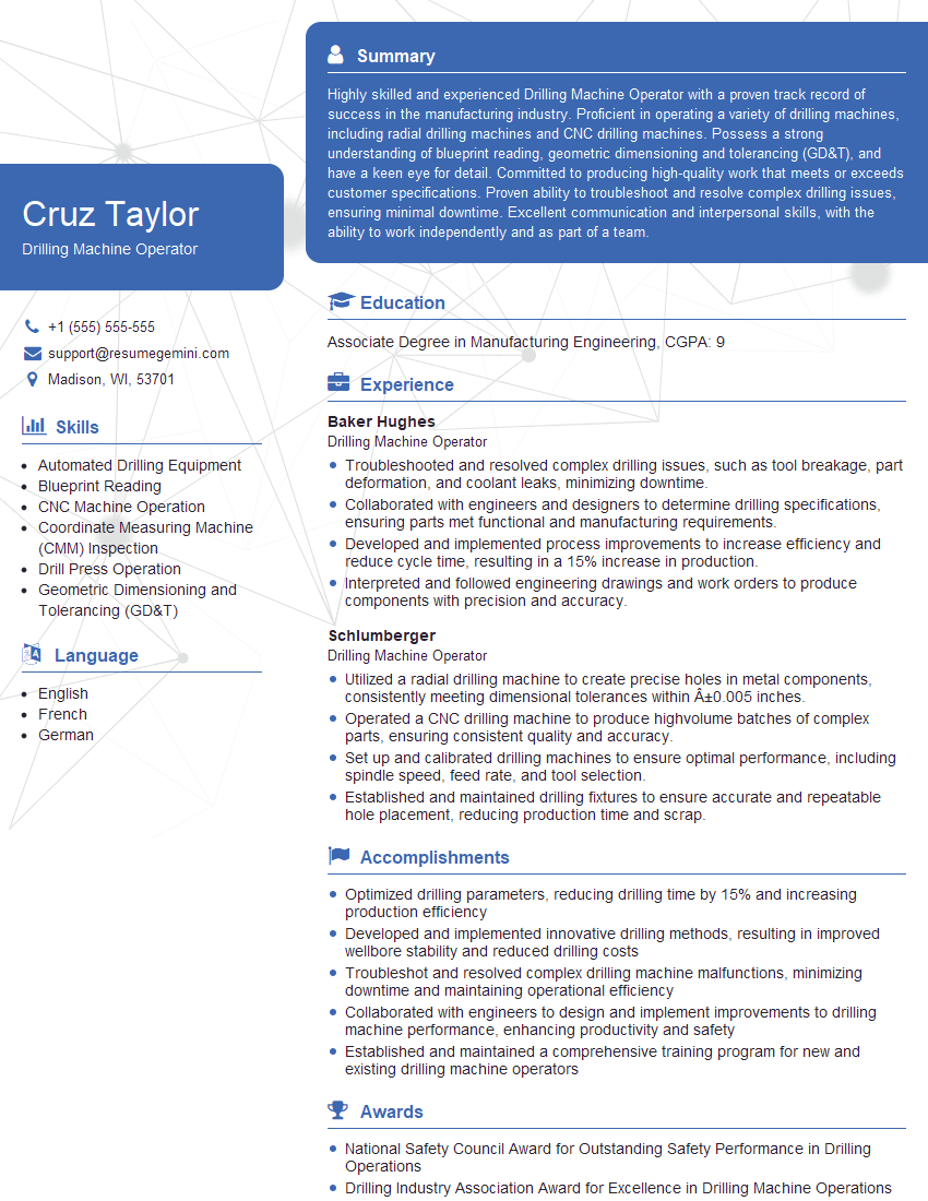
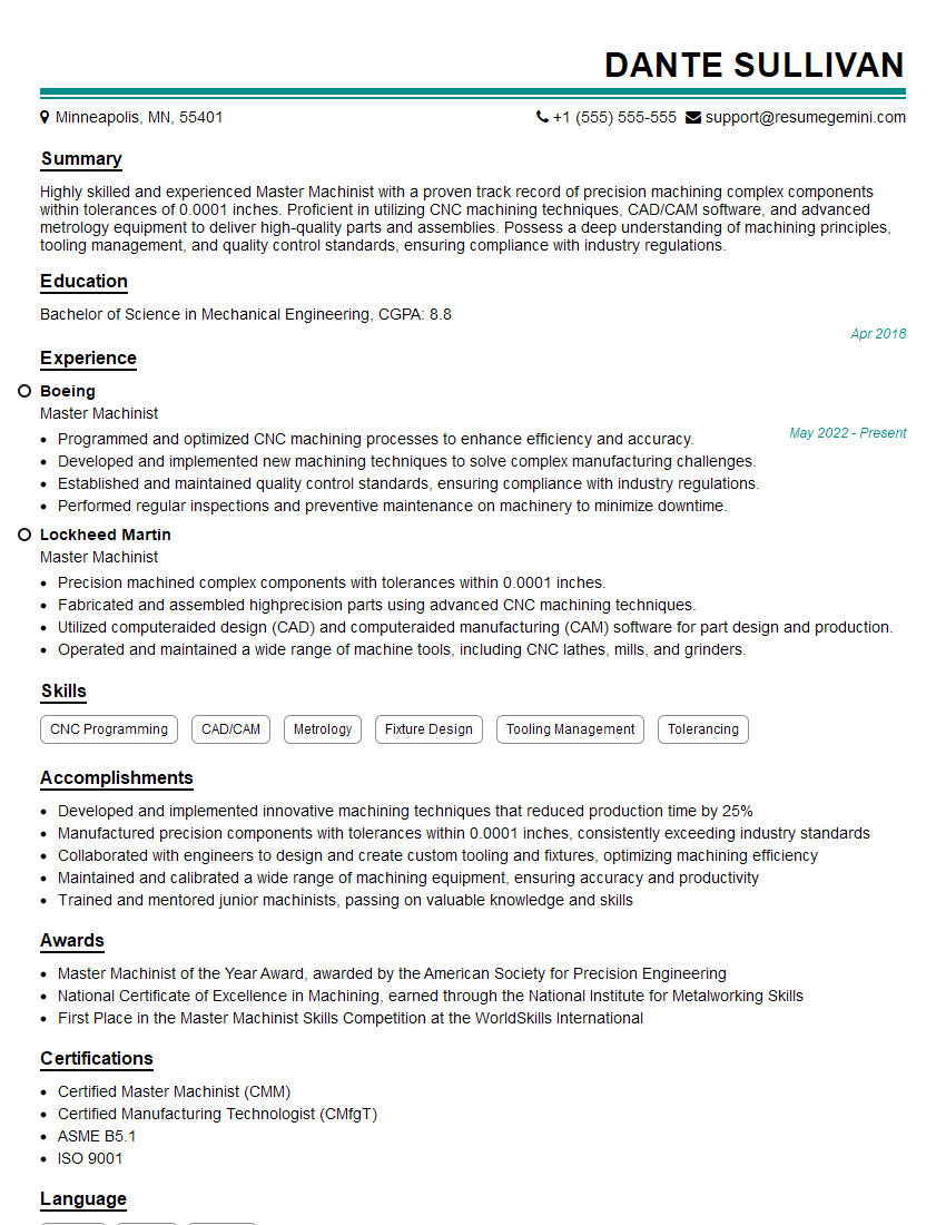
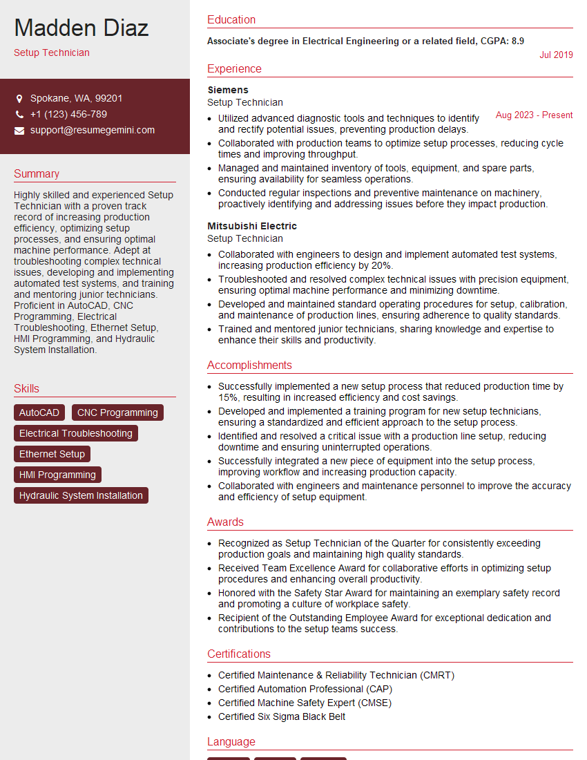
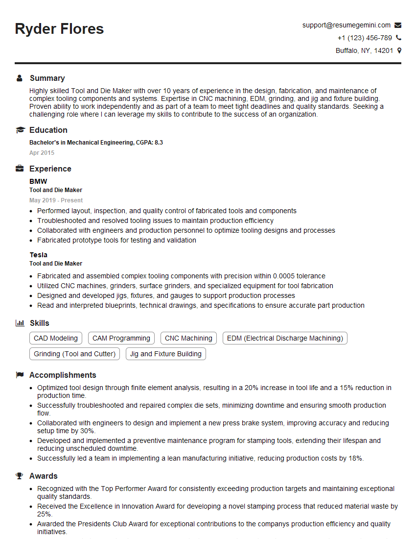
Mastering Hole Making and Layout Planning is crucial for advancing your career in manufacturing and related fields. These skills demonstrate precision, attention to detail, and problem-solving abilities – highly valued attributes in many industries. To maximize your job prospects, create a strong, ATS-friendly resume that highlights your expertise. ResumeGemini is a trusted resource that can help you build a professional and effective resume tailored to your skills. Examples of resumes tailored to Hole Making and Layout Planning are available to help guide you.
Explore more articles
Users Rating of Our Blogs
Share Your Experience
We value your feedback! Please rate our content and share your thoughts (optional).
What Readers Say About Our Blog
Hi, I’m Jay, we have a few potential clients that are interested in your services, thought you might be a good fit. I’d love to talk about the details, when do you have time to talk?
Best,
Jay
Founder | CEO
