The thought of an interview can be nerve-wracking, but the right preparation can make all the difference. Explore this comprehensive guide to Part and Tool Inspection interview questions and gain the confidence you need to showcase your abilities and secure the role.
Questions Asked in Part and Tool Inspection Interview
Q 1. Explain the difference between precision and accuracy in measurement.
Accuracy refers to how close a measurement is to the true value, while precision refers to how close repeated measurements are to each other. Think of it like shooting arrows at a target. High accuracy means your arrows are clustered near the bullseye, regardless of how spread out they are. High precision means your arrows are clustered closely together, but they might all be far from the bullseye. In part and tool inspection, both are crucial. A highly precise but inaccurate measurement is useless; we need both accurate and precise measurements to ensure parts meet specifications.
For example, if a part should be 10mm long, a measurement of 10.01mm is more accurate than a measurement of 9.95mm, however, repeated measurements of 10.01mm, 10.02mm, and 10.00mm exhibit high precision. In manufacturing, we strive for both—high accuracy and high precision to guarantee consistent quality.
Q 2. What are the common types of measuring instruments used in part and tool inspection?
The choice of measuring instrument depends heavily on the part’s complexity, size, and the required accuracy. Common tools include:
- Calipers (Vernier and Digital): Used for precise linear measurements of dimensions such as length, width, and depth.
- Micrometers: Provide even higher precision than calipers, ideal for measuring very small dimensions.
- Height Gauges: Used for precise height measurements, often with dial indicators for improved readability.
- Dial Indicators: Measure small displacements or variations in surface flatness.
- Surface Roughness Testers: Assess the texture of a surface.
- Optical Comparators: Project an enlarged image of a part to compare against a master template.
- Coordinate Measuring Machines (CMMs): Highly versatile for complex three-dimensional measurements.
Selecting the right instrument is key. Using a caliper for a micro-measurement would be inaccurate; a CMM might be overkill for a simple measurement of a bolt’s length.
Q 3. Describe your experience with CMM (Coordinate Measuring Machine) operation and programming.
I have extensive experience operating and programming various CMMs, including Renishaw and Zeiss models. My experience encompasses both touch-probe and scanning CMM technologies. In terms of programming, I’m proficient in creating measurement routines using dedicated CMM software (e.g., PC-DMIS, Calypso). I can develop programs to inspect complex geometries, including freeform surfaces and intricate features.
For example, I once developed a CMM program to inspect a highly complex automotive casting, which involved multiple features and required the use of various probing strategies to achieve the desired accuracy. The program was designed to automatically identify and report any deviations from the CAD model, improving efficiency and reducing human error significantly. I also have experience with GD&T (Geometric Dimensioning and Tolerancing) programming, ensuring accurate inspection against tolerance specifications.
Q 4. How do you interpret engineering drawings and specifications?
Interpreting engineering drawings and specifications requires a thorough understanding of technical drawing conventions, GD&T, and material specifications. I start by identifying the key dimensions, tolerances, and surface finish requirements, paying close attention to any notes or special instructions. I use my experience with CAD software (AutoCAD, SolidWorks) to visually correlate the drawing with the physical part, if necessary.
For instance, understanding GD&T symbols like position, runout, and flatness is crucial. A drawing might specify a positional tolerance of ±0.1mm. This means the feature must be within 0.1mm of its theoretical perfect location. This isn’t just about measurement; it’s about understanding the functional implications of those tolerances.
Q 5. What are your preferred methods for documenting inspection results?
My preferred methods for documenting inspection results prioritize clarity, traceability, and auditability. I use a combination of:
- Formal Inspection Reports: These include the part number, date, inspector’s name, measurement data, and a clear statement of whether the part conforms to the specifications.
- Digital Measurement Data: CMM and other digital instruments generate reports that are directly included in my formal report, providing traceability and supporting any findings.
- Photographic Documentation: Pictures of any deviations or discrepancies provide visual context and aid in understanding the findings.
- Statistical Process Control (SPC) Charts: These help track measurement trends over time and identify any potential process issues.
The goal is to make the results clear, concise, easily understood by both technical and non-technical personnel, and readily available for future reference.
Q 6. Explain your experience with different types of surface finish inspection techniques.
I’m familiar with several surface finish inspection techniques. These include:
- Visual Inspection: A quick assessment with a magnifying glass can often identify significant surface defects.
- Tactile Profilometry (Surface Roughness Testers): These instruments use a stylus to trace the surface and generate a profile, quantifying parameters like Ra (average roughness) and Rz (maximum peak-to-valley height).
- Optical Profilometry: Non-contact methods like confocal microscopy or interferometry offer high-resolution surface characterization.
The method used depends on the part’s requirements and the level of detail needed. For instance, a simple visual inspection may suffice for some parts, whereas critical aerospace components require precise measurement using a profilometer or optical techniques.
Q 7. How do you handle discrepancies found during inspection?
Handling discrepancies requires a systematic approach. The first step is to carefully re-check the measurements, verifying the calibration of instruments and the accuracy of the inspection process. If the discrepancy is confirmed, I then:
- Document the discrepancy thoroughly: This includes clear photographic evidence and detailed measurement data.
- Analyze the root cause: Is it a manufacturing error, a design issue, or a problem with the inspection process?
- Communicate the findings clearly: Inform the appropriate personnel (e.g., production supervisor, quality manager, engineering) in a timely manner.
- Recommend corrective actions: Suggest solutions based on the root cause analysis, whether it’s adjustments to the manufacturing process, redesign of the part, or re-calibration of instruments.
The objective is not just to identify a problem but to resolve it and prevent recurrence.
Q 8. Describe your experience with statistical process control (SPC).
Statistical Process Control (SPC) is a powerful methodology used to monitor and control the variability in a manufacturing process. It involves using statistical techniques to analyze data collected from the process, identify trends and patterns, and ultimately prevent defects. My experience with SPC spans several years, including implementing and maintaining control charts like X-bar and R charts, p-charts, and c-charts, depending on the type of data (continuous or attribute). For instance, in one project involving the production of precision ball bearings, we used X-bar and R charts to monitor the diameter of the bearings. By analyzing the data plotted on the control charts, we were able to quickly identify an issue with the machining process where tool wear was causing a gradual increase in the bearing diameter. This allowed for proactive tool changes, preventing a large batch of defective bearings.
Furthermore, I’m proficient in interpreting control chart patterns, recognizing signals of special cause variation (e.g., points outside control limits, trends, or runs) and common cause variation. Understanding these variations is crucial for deciding whether process adjustments are necessary or whether the variation is inherent to the system. This allows for targeted corrective actions rather than unnecessary process tweaks. I’ve also used SPC software such as Minitab to streamline data analysis and reporting, allowing for faster and more efficient process improvements.
Q 9. What are the common causes of dimensional variation in parts?
Dimensional variations in parts stem from a multitude of sources, broadly categorized as machine-related, material-related, and process-related factors. Machine-related causes include tool wear, machine vibration, improper machine setup, and inadequate maintenance. Imagine a lathe cutting a shaft; worn cutting tools will create a shaft that’s gradually larger than the specification. Material-related variations arise from inconsistencies in the raw material itself, such as variations in hardness, density, or chemical composition. For example, variations in the composition of a metal casting could lead to inconsistent dimensional stability.
Process-related causes are often the most challenging to control and include factors like variations in temperature, humidity, operator skill, and improper handling. Temperature fluctuations during a molding process can cause dimensional variations in plastic parts, while inconsistencies in operator technique can lead to variations in the assembly of components. Understanding these sources is key to implementing effective corrective measures. Addressing these issues often involves a systematic investigation using tools like Pareto charts to identify the most significant sources of variation.
Q 10. How do you identify and classify different types of defects?
Defect identification and classification are critical for effective quality control. Defects can be categorized using various methods, including classifications based on severity, type, and location. Severity can range from minor cosmetic defects to critical functional failures. Defect types can include surface imperfections like scratches, cracks, or pitting; dimensional inaccuracies such as excessive or insufficient size; or functional failures such as a malfunctioning part. Location might describe where on the part the defect is found.
I use a combination of visual inspection, dimensional measurement using various tools (discussed later), and sometimes non-destructive testing methods to identify defects. For example, a visual inspection might reveal scratches on a polished surface, while dimensional measurements with a micrometer would reveal if a part is outside its specified tolerance. A systematic approach and the use of standardized checklists and defect classification systems (e.g., using ISO standards) are crucial for consistent and reliable defect identification and reporting across different inspectors.
Q 11. Explain your experience with using various measuring tools (calipers, micrometers, height gauges).
I possess extensive experience using various measuring tools, including calipers, micrometers, and height gauges, to ensure parts meet the required specifications. Calipers are used for quick measurements of external and internal dimensions, as well as depths. Micrometers provide higher precision measurements for smaller dimensions, and height gauges are indispensable for accurately measuring the height or vertical distance of components. I’m proficient in selecting the appropriate tool for the measurement task at hand and understanding the limitations of each instrument. For example, I’d use calipers to check the overall length of a component, but a micrometer for precise measurements of shaft diameter or bore size. Proper handling and use are essential; familiarity with techniques like zeroing the micrometer before each measurement are crucial for obtaining accurate results.
Beyond the basic usage, I understand the importance of selecting the appropriate measuring instrument based on tolerance requirements and the complexity of the part. I am also well-versed in interpreting measurement uncertainty and error to ensure accurate assessment of dimensional conformance.
Q 12. How do you ensure the accuracy and calibration of measuring instruments?
Accuracy and calibration of measuring instruments are paramount. We use a robust calibration program to ensure all measuring tools are regularly checked and adjusted to maintain their accuracy. This involves comparing the instrument’s readings against traceable standards, often done using certified master gauges. Calibration frequency varies depending on the instrument’s type, usage frequency, and the criticality of the measurements being taken. Micrometers, for instance, usually require more frequent calibration than calipers.
Calibration records are meticulously maintained, providing a clear history of the instrument’s performance and ensuring traceability to national or international standards. Out-of-tolerance instruments are immediately tagged out of service and sent for recalibration or repair. This process is documented and reviewed regularly to ensure the integrity of our measurement system. Using uncalibrated instruments can lead to significant inaccuracies in part inspection and ultimately production of non-conforming parts.
Q 13. Describe your experience with first article inspection.
First Article Inspection (FAI) is a crucial process in manufacturing, ensuring that the first production run of a part conforms to the design specifications and the quality requirements. My experience with FAI includes meticulously examining the initial production sample(s) against the approved drawings and specifications. This includes verifying dimensions, material properties, surface finish, and functionality. I’ve been involved in creating and completing FAI reports, which meticulously document the inspection findings and include supporting evidence such as photographs or measurement data. Any discrepancies between the inspected part and the specifications are immediately flagged and reported.
Effective FAI prevents potential problems down the line and is essential for securing production approval. The FAI report serves as a critical document for the entire manufacturing process, ensuring that everyone involved understands the quality standards to be maintained. I’ve found that a well-organized FAI process, combined with clear communication, is essential for ensuring a smooth start to production.
Q 14. How do you prioritize inspection tasks in a high-volume production environment?
Prioritizing inspection tasks in a high-volume production environment is crucial for optimizing resources and ensuring timely product delivery. I use a risk-based approach, prioritizing parts or processes with the highest potential impact on product quality or customer satisfaction. This involves considering factors such as the criticality of the part’s function, the historical defect rate, and the potential consequences of a defect. Critical components, those with a history of defects, or those crucial for product safety are prioritized. A system of sampling plans and statistical analysis can aid in optimizing inspection frequency while still ensuring adequate quality control.
For instance, using AQL (Acceptable Quality Limit) sampling plans helps determine the appropriate sample size based on the acceptable level of defects in a batch. Automation and the use of automated inspection systems are critical in high-volume settings, allowing for rapid and consistent inspection of many parts, freeing up human inspectors to focus on more complex or critical tasks. Effective communication and collaboration across teams are essential for efficient task prioritization and resource allocation in a busy manufacturing setting.
Q 15. Explain your understanding of GD&T (Geometric Dimensioning and Tolerancing).
GD&T, or Geometric Dimensioning and Tolerancing, is a symbolic language used on engineering drawings to define the size, shape, orientation, location, and runout of features on a part. It goes beyond simple plus/minus tolerances by specifying the permissible variation in a more precise and unambiguous way. Instead of just stating a diameter tolerance, for example, GD&T can specify the allowed deviation in circularity, position, and perpendicularity of that diameter. This leads to clearer communication between designers, manufacturers, and inspectors, minimizing misunderstandings and improving part quality.
For example, imagine a hole that needs to be precisely positioned relative to another feature. A simple tolerance might specify the hole’s diameter, but GD&T would allow you to specify the hole’s position using a positional tolerance zone, ensuring it’s within an acceptable range from the reference feature, even if its diameter varies slightly within its tolerance.
- Size Tolerance: Defines the allowable variation in the dimension of a feature (e.g., diameter, length).
- Form Tolerance: Controls the shape of a single feature (e.g., straightness, flatness, circularity).
- Orientation Tolerance: Specifies the allowable angular variation of a feature (e.g., perpendicularity, angularity).
- Location Tolerance: Defines the permissible deviation of a feature’s location relative to another feature (e.g., position, concentricity).
- Runout Tolerance: Controls the variation of a feature’s surface as it rotates or moves along an axis (e.g., circular runout, total runout).
Career Expert Tips:
- Ace those interviews! Prepare effectively by reviewing the Top 50 Most Common Interview Questions on ResumeGemini.
- Navigate your job search with confidence! Explore a wide range of Career Tips on ResumeGemini. Learn about common challenges and recommendations to overcome them.
- Craft the perfect resume! Master the Art of Resume Writing with ResumeGemini’s guide. Showcase your unique qualifications and achievements effectively.
- Don’t miss out on holiday savings! Build your dream resume with ResumeGemini’s ATS optimized templates.
Q 16. How do you use your knowledge of GD&T to evaluate part conformance?
Evaluating part conformance using GD&T involves carefully examining each feature specified on the engineering drawing against the defined tolerances. This typically involves using precision measuring instruments like CMMs (Coordinate Measuring Machines), optical comparators, calipers, and micrometers. I meticulously check each GD&T symbol and its associated tolerance value. I would utilize appropriate inspection equipment to measure the actual part features and compare them to the GD&T specifications on the drawing. Statistical process control (SPC) charts are frequently used to track measurement data and ensure consistent part quality. Any deviation outside the specified tolerances indicates non-conformance.
For instance, if a drawing specifies a positional tolerance of ±0.1mm for a hole relative to a datum, I would measure the hole’s actual position using a CMM and verify that it falls within the defined zone. If the measurement falls outside the tolerance zone, the part is deemed non-conforming. Documentation of all measurements and findings is crucial for traceability and quality control.
Q 17. Describe your experience with using optical comparators or other similar inspection tools.
I have extensive experience using optical comparators, which are invaluable for inspecting parts with complex geometries and intricate features. I’ve used them to verify dimensions, profiles, angles, and overall shape conformance to design specifications. Optical comparators project a magnified image of the part onto a screen, allowing for precise visual comparison against a master template or blueprint. This method is especially useful for identifying minute deviations in part geometry. Besides optical comparators, I’m also proficient with various other inspection tools, including CMMs, vision systems, profilometers and micro-scopes. Each tool offers unique advantages depending on the part complexity and required precision.
For example, when inspecting a small, intricate gear, I would use an optical comparator to quickly check the profile of each tooth, ensuring that the shape and spacing conform to the drawing. A CMM would then be used to obtain more precise measurements of critical dimensions such as tooth thickness and overall diameter.
Q 18. How do you handle non-conforming parts or tools?
Handling non-conforming parts or tools involves a systematic approach that ensures quality control and prevents further issues. The first step is to clearly document the non-conformity, including detailed measurements and observations. I would then visually inspect the tools for any damage or wear that may have contributed to the problem. Following a thorough investigation, I would classify the non-conformity (minor or major) according to the company’s quality procedures. For minor non-conformances, repair or rework may be possible, subject to approval. Major non-conformances usually result in part rejection and a detailed non-conformance report is issued, including the corrective actions required. This report is used to initiate the root cause analysis process.
Rejected parts are typically segregated and handled according to company procedures, which might involve scrapping, rework, or returning them to the supplier. The goal is to prevent these non-conforming items from entering the supply chain or getting used in production.
Q 19. What are your methods for identifying root causes of inspection failures?
Identifying root causes of inspection failures requires a structured approach. I typically use a combination of methods, including the 5 Whys technique, fishbone diagrams (Ishikawa diagrams), and Pareto analysis. The 5 Whys involves repeatedly asking “why” to drill down to the underlying cause of the failure. Fishbone diagrams help to visually organize potential contributing factors categorized by categories such as materials, methods, machines, manpower, measurement, and environment. Pareto analysis helps to identify the most significant factors contributing to the majority of failures.
For instance, if a batch of parts fails to meet the positional tolerance for a hole, I would use these techniques to investigate potential causes. Asking “Why?” repeatedly may reveal issues with machine calibration, tooling wear, operator error, or problems with the raw materials.
Q 20. Explain your experience with implementing corrective actions to prevent recurring inspection failures.
Implementing corrective actions to prevent recurring inspection failures is a crucial step in maintaining consistent quality. Once the root cause of a failure has been identified, appropriate corrective actions are developed and implemented. These actions should be documented and tracked to ensure their effectiveness. Corrective actions may involve recalibrating equipment, replacing worn tools, revising inspection procedures, providing additional operator training, or making changes to the manufacturing process. The effectiveness of the corrective actions is then monitored through ongoing inspection and data analysis to ensure the problem is resolved and does not reoccur.
For example, if worn tooling was identified as the root cause of a recurring dimensional problem, corrective actions would include replacing the worn tool and potentially implementing a more robust tool maintenance program to prevent future failures.
Q 21. How do you maintain a clean and organized inspection area?
Maintaining a clean and organized inspection area is paramount for accurate and efficient work. A clean environment minimizes the risk of contamination, reduces the possibility of damaging parts or tools, and ensures that measurements are not compromised. My approach involves regularly cleaning and disinfecting work surfaces and equipment. Tools and measuring instruments are carefully stored in designated areas to prevent damage and misplacement. The inspection area is organized to ensure efficient workflow, with clearly marked zones for different tasks. A visual management system may be used to help maintain organization and identify potential problems quickly. Regular audits and visual inspections are conducted to ensure the area remains clean, tidy and well-maintained.
This systematic approach to cleanliness and organization contributes to a safe, efficient, and accurate inspection process, which is essential for ensuring product quality.
Q 22. Describe your experience with different types of inspection reports.
Throughout my career, I’ve worked extensively with various inspection reports, each tailored to specific needs and industries. These range from simple check sheets for visual inspections to complex, data-rich reports generated by sophisticated Coordinate Measuring Machines (CMMs) or automated optical inspection (AOI) systems.
- Simple Check Sheets: These are used for quick visual checks, noting surface finish, dimensions with simple measuring tools (calipers, micrometers), and the presence or absence of defects. For example, in a manufacturing plant producing simple metal parts, a check sheet might track whether each part has the correct number of holes, and if those holes are free of burrs.
- CMM Reports: These reports provide highly accurate dimensional measurements, often including geometric dimensioning and tolerancing (GD&T) analysis. CMM reports frequently include deviation from nominal values, statistical process control (SPC) charts showcasing process stability, and visualizations such as point clouds or cross-sections. Imagine a scenario where we’re inspecting a complex aerospace component; a CMM report would detail the precise location and size of every feature, flagging any deviations from the CAD model.
- AOI Reports: Automated Optical Inspection systems generate reports documenting defects detected through image analysis. These reports often include images of the detected flaws, location coordinates, and classification of defects (e.g., scratches, pits, cracks). In the electronics industry, for instance, AOI reports are critical for detecting microscopic solder defects on printed circuit boards.
- Non-Destructive Testing (NDT) Reports: These reports document findings from techniques like ultrasonic testing, radiography, or magnetic particle inspection. They often include images and interpretations of the test results, highlighting potential internal flaws or inconsistencies. This type of report would be crucial for inspecting welds in pipelines or pressure vessels.
My experience encompasses generating, interpreting, and using these diverse reports to identify issues, track quality, and improve manufacturing processes.
Q 23. How do you work effectively within a team environment during inspections?
Effective teamwork is paramount in part and tool inspection. I thrive in collaborative environments, contributing my expertise while actively listening to and valuing the perspectives of my colleagues. My approach focuses on clear communication, shared responsibility, and mutual respect.
- Clear Communication: Before any inspection, we discuss the scope, objectives, and methodologies, ensuring everyone is on the same page. During the inspection, we maintain open communication, sharing observations and potential discrepancies promptly.
- Shared Responsibility: We divide tasks logically based on individual strengths and expertise, ensuring thorough coverage of all aspects of the inspection. This might involve one team member focusing on dimensional accuracy while another handles surface finish analysis.
- Mutual Respect: I encourage a culture of open dialogue and constructive criticism. We actively discuss findings and potential interpretations, acknowledging that differing viewpoints can lead to a more comprehensive understanding of the results. If disagreements arise, we use a collaborative problem-solving approach to reach consensus.
For example, during a recent inspection of a large assembly, our team leveraged each member’s unique skills: one specializing in GD&T interpretation, another in NDT, and myself focusing on dimensional measurement with CMM. Through clear communication and division of labor, we identified a critical alignment issue early on, preventing further production problems.
Q 24. What are your strengths and weaknesses in relation to part and tool inspection?
My strengths lie in my meticulous attention to detail, my proficiency in utilizing various inspection techniques, and my ability to interpret complex data effectively. My weaknesses include a tendency to be perfectionistic (which I’m actively working to manage) and occasional challenges in adapting to entirely new inspection technologies without dedicated training.
- Strengths: I’m adept at using a wide range of equipment including CMMs, optical comparators, microscopes, and various measuring tools. I possess strong analytical skills, enabling me to identify subtle defects and discrepancies in data. I also excel at generating clear, concise, and comprehensive inspection reports that meet both internal and external quality standards.
- Weaknesses: My strong desire for accuracy sometimes leads to spending more time on an inspection than is strictly necessary. I’m addressing this by learning time management techniques and prioritizing tasks. My familiarity with cutting-edge technologies is ever-evolving. I actively address this by participating in training and staying updated with relevant literature and industry events.
For instance, while I’m highly proficient with CMMs, the introduction of a new laser scanning system initially presented a learning curve. I proactively sought additional training and now feel comfortable operating and interpreting data from this technology.
Q 25. How do you stay up-to-date with the latest advancements in inspection technologies?
Staying current with advancements in inspection technologies is vital in this rapidly evolving field. I employ a multifaceted approach to continuous learning:
- Industry Conferences and Trade Shows: Attending industry events allows me to network with other professionals, learn about new products, and see live demonstrations of cutting-edge equipment.
- Professional Development Courses and Webinars: I regularly participate in online and in-person training courses focusing on new inspection techniques, software, and data analysis methods.
- Professional Publications and Journals: I subscribe to and regularly read industry publications and journals to stay informed about the latest research and technological breakthroughs.
- Manufacturer Training and Workshops: I participate in training offered by equipment manufacturers to enhance my understanding of their specific technologies and best practices.
- Online Resources and Communities: I leverage online forums, communities, and websites dedicated to part and tool inspection to engage with colleagues and learn from their experiences.
This proactive approach ensures my skills remain sharp, and I’m capable of utilizing the most efficient and effective techniques in my work.
Q 26. Describe your experience with using software for data analysis in inspection.
I’ve extensive experience using software for data analysis in inspection, utilizing various statistical process control (SPC) software and CAD/CAM packages. My skills include data extraction, statistical analysis, report generation and visualization.
- SPC Software: I’m proficient in using software like Minitab or JMP to analyze dimensional data from CMMs or other measuring equipment, identifying trends, generating control charts, and determining process capability. For example, I used Minitab to analyze data from a CMM inspection, identifying a trend of increasing part diameter, which subsequently led to process adjustments and improved part quality.
- CAD/CAM Software: I use CAD software to compare inspection data with the original design specifications, identifying discrepancies and generating reports detailing the deviations. This often involves importing CMM data directly into the CAD model for accurate comparison.
- Custom Databases and Spreadsheets: I’ve developed custom databases and spreadsheets to manage and analyze large datasets generated by different inspection methods. This allows for efficient tracking of inspection results, identification of recurring issues, and analysis of overall process performance.
My experience with these tools allows for robust data analysis, leading to faster problem identification, more efficient process improvements, and overall enhanced product quality.
Q 27. How do you ensure the confidentiality and integrity of inspection data?
Maintaining the confidentiality and integrity of inspection data is crucial, especially considering the sensitive nature of much of the information. My approach is multi-pronged:
- Secure Data Storage: Inspection data is stored on secure servers with restricted access, utilizing password protection and encryption to prevent unauthorized access. Physical security measures are also implemented where relevant.
- Access Control: Access to inspection data is strictly controlled, granted only to authorized personnel on a need-to-know basis. Access logs are meticulously maintained to track data access history.
- Data Backup and Recovery: Regular data backups are conducted to prevent data loss due to equipment failure or other unforeseen circumstances. Secure offsite storage ensures data redundancy and protection.
- Data Integrity Measures: We use version control systems to track changes in inspection data and prevent accidental or malicious alterations. Data validation checks are implemented to ensure data accuracy and consistency.
- Compliance with Regulations: All data handling practices adhere to relevant industry regulations and company policies regarding data privacy and security. For example, we follow ISO 9001 and AS9100 guidelines for quality management systems.
This comprehensive approach ensures that inspection data remains confidential, accurate, and readily available when needed while fully adhering to both legal and ethical standards.
Key Topics to Learn for Part and Tool Inspection Interview
- Dimensional Measurement Techniques: Understanding various measuring instruments (calipers, micrometers, CMMs), their precision, and proper usage. Practical application includes performing accurate measurements on various parts and documenting findings.
- Geometric Dimensioning and Tolerancing (GD&T): Interpreting GD&T symbols and specifications on engineering drawings. Practical application involves verifying part conformance to design specifications using GD&T principles.
- Surface Finish Inspection: Identifying and classifying surface imperfections (roughness, waviness). Practical application includes using surface roughness measuring instruments and assessing their impact on part functionality.
- Material Identification and Testing: Recognizing different materials (metals, plastics, composites) and understanding basic material testing methods. Practical application involves using material testing equipment (e.g., hardness testers) to verify material properties.
- Tool Inspection and Maintenance: Inspecting tools for wear, damage, and proper calibration. Practical application includes identifying faulty tools and implementing preventative maintenance procedures.
- Statistical Process Control (SPC): Understanding basic SPC concepts and their application in monitoring part and tool quality. Practical application includes interpreting control charts and identifying trends indicating process variation.
- Quality Control Documentation and Reporting: Accurately documenting inspection results, identifying defects, and creating clear and concise reports. Practical application includes following company procedures for reporting non-conformances and contributing to continuous improvement efforts.
- Problem-Solving and Root Cause Analysis: Identifying the root causes of part or tool defects and proposing solutions to prevent recurrence. Practical application involves using problem-solving methodologies (e.g., 5 Whys) to address quality issues.
Next Steps
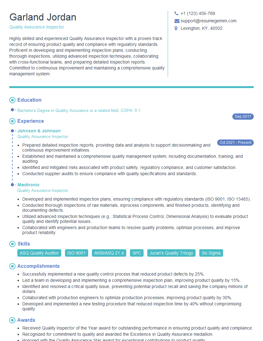
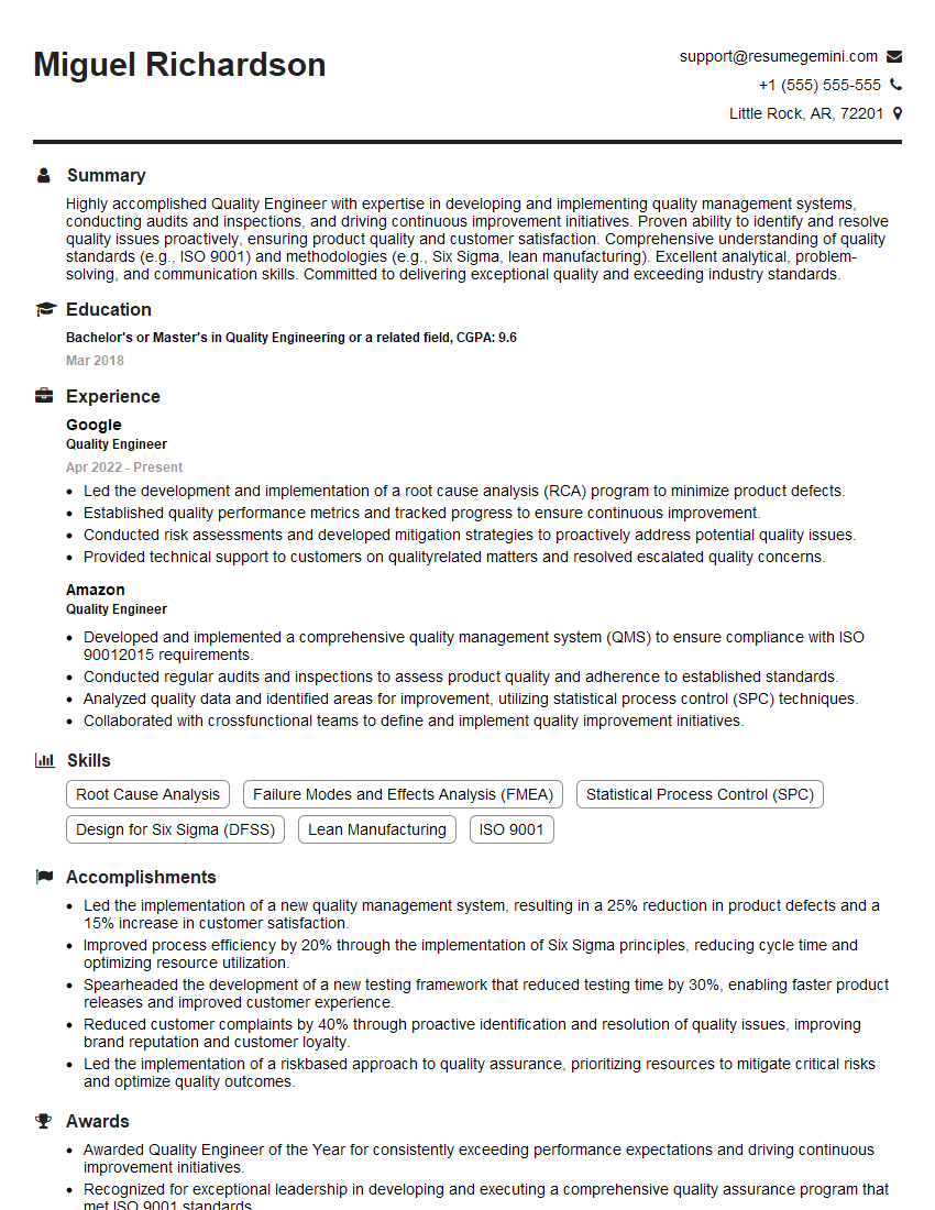
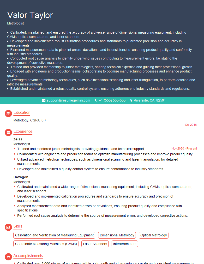
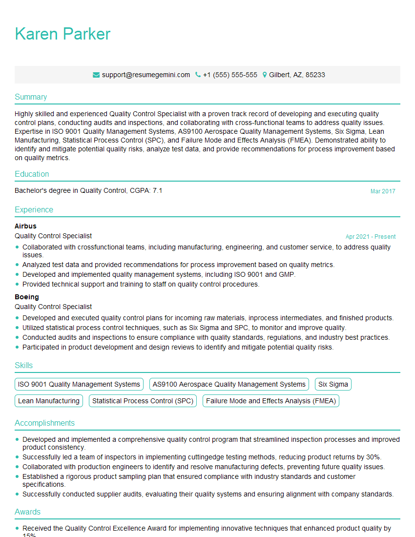
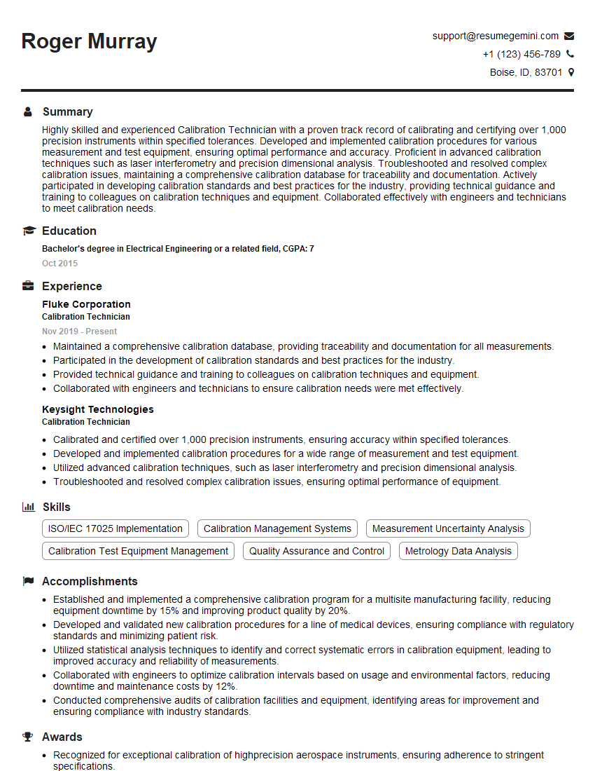
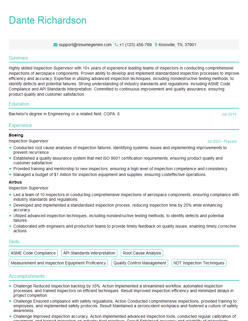
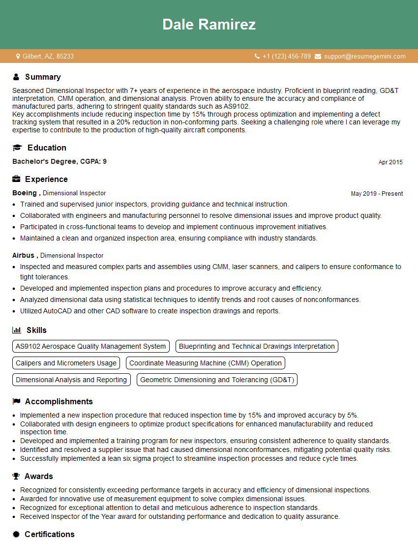
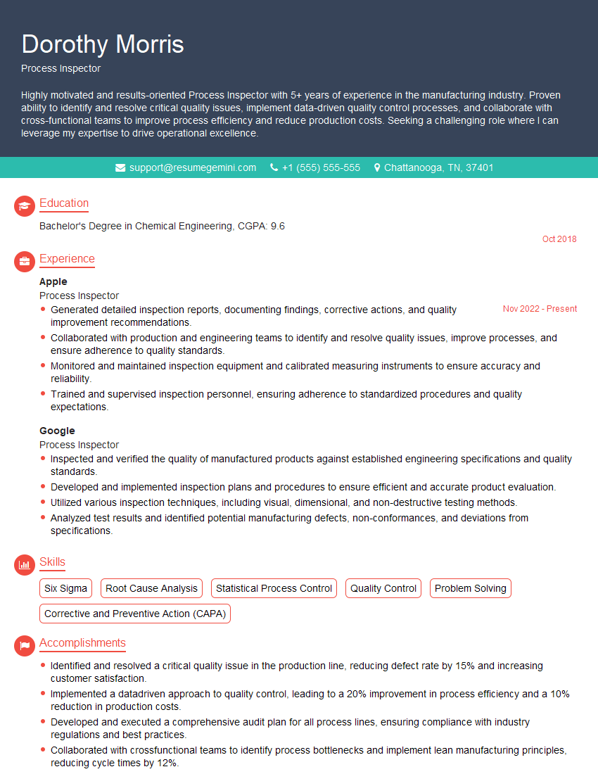
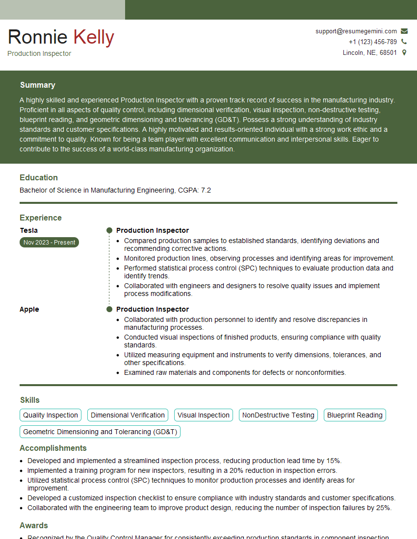
Mastering Part and Tool Inspection opens doors to a rewarding career with excellent growth potential, offering opportunities for advancement into specialized roles within quality control, manufacturing engineering, or management. To maximize your job prospects, creating a strong, ATS-friendly resume is crucial. ResumeGemini is a trusted resource to help you build a professional and impactful resume that highlights your skills and experience. Examples of resumes tailored specifically to Part and Tool Inspection are available to guide you in showcasing your qualifications effectively.
Explore more articles
Users Rating of Our Blogs
Share Your Experience
We value your feedback! Please rate our content and share your thoughts (optional).
What Readers Say About Our Blog
Hi, I’m Jay, we have a few potential clients that are interested in your services, thought you might be a good fit. I’d love to talk about the details, when do you have time to talk?
Best,
Jay
Founder | CEO
