Feeling uncertain about what to expect in your upcoming interview? We’ve got you covered! This blog highlights the most important HyperMill or Mastercam Software interview questions and provides actionable advice to help you stand out as the ideal candidate. Let’s pave the way for your success.
Questions Asked in HyperMill or Mastercam Software Interview
Q 1. Explain the difference between roughing and finishing strategies in HyperMill.
In HyperMill, roughing and finishing strategies are distinct phases in the machining process, each with a specific goal. Roughing focuses on quickly removing large amounts of material, prioritizing speed and efficiency. Finishing, on the other hand, prioritizes surface quality and accuracy, removing only minimal material to achieve the desired surface finish.
Roughing: Think of it like sculpting with a sledgehammer. We use aggressive tools and high feed rates to rapidly remove material. Common roughing strategies in HyperMill include Adaptive Clearing (for complex shapes) and Waterline Roughing (for efficient material removal along a defined boundary). Toolpaths are often less precise, resulting in a rough surface that needs further refinement.
Finishing: Now, imagine refining your sculpture with a fine chisel. Finishing utilizes smaller tools and shallower cuts at slower feed rates, ensuring precision and a smooth surface. Common finishing strategies include High-Speed Finishing (for smooth surfaces) and Trace Milling (for following the part geometry precisely). The goal is a high-quality surface free from tool marks.
Example: Imagine machining a complex aluminum part. We’d start with a roughing strategy like Adaptive Clearing to quickly remove the majority of the material, then switch to a finishing strategy like High-Speed Finishing to produce a smooth, accurate surface ready for use.
Q 2. Describe your experience with Mastercam’s toolpath simulation.
My experience with Mastercam’s toolpath simulation is extensive. I rely heavily on it for verifying toolpaths before sending them to the machine. It’s invaluable for preventing costly errors. Mastercam’s simulation allows for a realistic preview of the machining process, including tool movements, cutting depths, and potential collisions. I can observe the machine’s behavior virtually, identifying and correcting issues like gouges, excessive tool deflection, or spindle speed issues, *before* they occur on the actual part.
For instance, I once used the simulation to identify a potential collision between the tool and a fixture on a complex automotive part. This early detection saved significant time and prevented damage to both the part and the machine. The detailed visualization provides confidence in the generated toolpaths, reducing the risk of errors and improving overall shop floor efficiency.
Q 3. How do you optimize toolpaths for efficient material removal in HyperMill?
Optimizing toolpaths in HyperMill for efficient material removal involves a multi-faceted approach. It’s not just about speed; it’s about balancing speed, surface finish, and tool life.
- Selecting Appropriate Strategies: Choosing the right roughing and finishing strategies (like Adaptive Clearing or Waterline for roughing, and High-Speed Finishing or Flowline for finishing) is crucial. Each strategy has strengths for different geometries and material properties.
- Tool Selection: Using tools with appropriate diameters and geometries for different stages of machining is critical. Larger diameter tools for roughing, smaller ones for finishing.
- Stepover Optimization: Finding the optimal stepover (distance between adjacent toolpaths) is key. A smaller stepover ensures better surface finish but increases machining time. Conversely, larger stepovers increase speed but potentially compromise surface quality.
- Stock Definition: Accurate stock definition helps the software determine the material to be removed efficiently, preventing unnecessary cuts.
- Parameter Tuning: Adjusting parameters like feed rates, spindle speeds, and depth of cut based on the material being machined and the selected tools significantly impacts material removal rate and tool life. Experimentation and iterative refinement are crucial.
For example, when machining titanium, I’d prioritize conservative stepovers and feed rates to extend tool life, even if it means a slightly longer machining time. For aluminum, I can be more aggressive to improve material removal rate without significantly impacting tool life.
Q 4. What are the different types of toolpath strategies available in Mastercam?
Mastercam offers a wide array of toolpath strategies, catering to diverse machining needs. These strategies can be broadly categorized as:
- Roughing Strategies: These include Adaptive Clearing, Parallel, Contour, and Rest Machining. Each focuses on removing large amounts of material efficiently, employing various methods for optimizing toolpaths and avoiding collisions.
- Finishing Strategies: Options include High-Speed Finishing, Flowline, Surface Finishing, and Curve-Based Machining. These prioritize surface quality and precision, utilizing various techniques to produce smooth and accurate surfaces.
- Drilling Strategies: Mastercam provides tools for creating drilling toolpaths, including pecking, drilling, and spot drilling, addressing different hole types and materials.
- 3D Strategies: For complex three-dimensional parts, Mastercam offers sophisticated strategies like 3D Adaptive Clearing and 3D Finishing to handle complex surfaces and curves.
- Turning Strategies: Mastercam also offers several strategies specifically for turning operations.
The selection of the appropriate strategy greatly depends on factors like the part geometry, the material being machined, the desired surface finish, and the available tooling.
Q 5. How do you handle complex geometries in HyperMill or Mastercam?
Handling complex geometries in HyperMill and Mastercam involves a systematic approach:
- Tessellation: Understanding the software’s approach to tessellating complex surfaces – breaking them down into smaller, manageable facets – is crucial. The level of tessellation influences the accuracy and smoothness of the toolpath.
- Strategy Selection: Selecting the appropriate toolpath strategy is vital. Adaptive clearing strategies in both HyperMill and Mastercam excel at handling complex curves and free-form surfaces by dynamically adjusting toolpaths to match geometry.
- Toolpath Simulation: Always use simulation to verify toolpaths, especially on complex parts, to identify and rectify potential gouges or collisions.
- Tool Selection: Employing the right tools – perhaps smaller tools for tighter curves and larger tools for open areas – ensures a balance between efficiency and precision.
- Multi-pass Strategies: Breaking the machining process into multiple passes, starting with roughing to remove bulk material and progressing to finishing for smooth surfaces, is often necessary for complex shapes. This ensures better control and prevents inaccuracies.
For instance, I’ve successfully machined intricate turbine blades using adaptive clearing in HyperMill, optimizing toolpaths to achieve the desired tolerances while avoiding any collisions.
Q 6. Explain your experience with stock definition in CAM software.
Stock definition is a cornerstone of efficient CAM programming. It’s the process of defining the starting material’s shape and size within the CAM software. An accurate stock definition is paramount because it dictates the material the software needs to remove to create the finished part. An inaccurate definition can lead to gouges, tool breakage, or incomplete machining.
My process involves several steps:
- Accurate Measurement: Begin with precise measurements of the raw material’s dimensions – length, width, and height.
- Importing Geometry: I import the stock geometry into the CAM software. This is typically a simple solid or block representing the raw material. HyperMill and Mastercam offer different methods for stock definition – drawing a block, importing a CAD model representing the stock, or even directly scanning the stock piece using a 3D scanner.
- Verification: After defining the stock, I visually inspect it within the software to ensure it accurately represents the real-world stock. A mistake here can have significant downstream consequences.
- Stock Model Updates: As the machining process progresses, particularly in multi-operation setups, I often update the stock model to reflect the material already removed. This prevents unnecessary toolpaths and collision.
In essence, accurate stock definition is crucial for minimizing waste, maximizing efficiency, and ultimately preventing costly mistakes on the shop floor.
Q 7. Describe your process for creating and managing tool libraries in HyperMill or Mastercam.
Creating and managing tool libraries is essential for streamlining the CAM programming process and ensuring consistency. In HyperMill and Mastercam, I follow a meticulous approach:
- Organization: I organize tool libraries by tool type (end mills, drills, reamers, etc.) and material type (steel, aluminum, titanium). This makes it easy to find specific tools.
- Detailed Information: Each tool entry includes detailed information: manufacturer, model number, diameter, length, cutting edge geometry, coating, and recommended cutting parameters (feed rate, spindle speed, depth of cut).
- Regular Updates: I regularly update the tool library as new tools are acquired or existing tools are replaced. This ensures the library remains accurate and up-to-date.
- Version Control: For large projects, I employ version control to track changes made to the tool library. This allows me to revert to previous versions if necessary.
- Data Backup: Regular backups of the tool library are essential to prevent data loss. This is especially important given the time and effort invested in creating the library.
A well-organized and maintained tool library significantly improves efficiency, reducing the time spent searching for tool data and minimizing the risk of errors caused by inaccurate tool information.
Q 8. How do you verify toolpath accuracy in your CAM software?
Verifying toolpath accuracy is crucial for preventing costly mistakes. In HyperMill and Mastercam, I employ a multi-pronged approach. Firstly, I always visually inspect the toolpath simulation in 3D. This allows me to quickly identify obvious errors like gouges or collisions. Think of it like a pre-flight check for an airplane – you wouldn’t take off without a thorough inspection! Secondly, I utilize the software’s built-in verification tools, which provide detailed information on tool movements, including clearances, depths, and feedrates. These often generate reports with graphical representations of potential issues. Finally, for complex parts, I perform a ‘dry run’ using a non-destructive material, like wax or a soft metal, to validate the toolpath before machining the final workpiece. This final step is especially important for high-value parts or those with intricate geometries.
For example, in HyperMill, the ‘Verify’ function, along with the stock model, lets me see precisely how the tool interacts with the material. Any potential collision or gouge is highlighted, making corrections straightforward.
Q 9. What are the different types of post-processors and how do you select the appropriate one?
Post-processors are essentially translators between the CAM software and your specific CNC machine. They convert the toolpath data into a language the machine’s controller understands. There are numerous types, each tailored to a particular CNC brand and model (e.g., Fanuc, Haas, Siemens). Factors like the machine’s control system (e.g., G-code, ISO), its capabilities (e.g., number of axes, rotary tables), and its specific requirements (e.g., coolant settings, spindle speed limits) dictate which post-processor you select.
Choosing the wrong post-processor can lead to machine errors, incorrect tool movements, and even machine damage. The selection process involves carefully reviewing the CNC machine’s manual and choosing the post-processor explicitly designed for its make and model. Mastercam and HyperMill often have extensive post-processor libraries, but customization may be needed for specific machine configurations.
Imagine it like selecting the correct language translator for a business meeting. The wrong translator could lead to misunderstandings with disastrous consequences!
Q 10. Explain your experience with collision detection in HyperMill or Mastercam.
Collision detection is a paramount safety feature. Both HyperMill and Mastercam offer sophisticated collision detection systems. In HyperMill, I frequently use the ‘Collision Check’ function during toolpath simulation. This function analyzes the toolpaths against the fixture, the workpiece, and the machine itself, highlighting any potential clashes. Similarly, Mastercam’s collision detection system offers both simulation and analysis features, allowing me to identify and resolve potential collisions before they occur.
I’ve had several instances where collision detection saved the day. One project involved a complex five-axis machining operation with numerous tools and a multi-part fixture. The software alerted me to a potential collision between the tool and a clamping mechanism, preventing a costly and potentially dangerous incident. Addressing these collisions proactively saves time, materials, and prevents damage to the machine.
Q 11. How do you handle undercuts and complex features in your CAM programming?
Undercuts and complex features require strategic planning and a thorough understanding of machining techniques. I often use a combination of strategies, including multiple setups, specialized toolpaths, and advanced machining techniques. For undercuts, I might employ multiple setups, carefully orienting the workpiece to allow access to all surfaces. Alternatively, I might utilize specialized toolpaths, such as 3+2 axis machining or 5-axis simultaneous machining, allowing the tool to move around obstructions and machine difficult-to-reach areas. For complex features with deep pockets or intricate geometries, I use high-speed machining (HSM) strategies to optimize cutting parameters for efficient and smooth surface finishes.
Consider creating a step-by-step plan. Think of it like solving a 3D jigsaw puzzle, needing to determine the optimal sequence of cuts to reach all pieces.
Q 12. Describe your experience with multi-axis machining in HyperMill or Mastercam.
My experience with multi-axis machining is extensive. I’m proficient in both 3+2 axis and full 5-axis simultaneous machining in both HyperMill and Mastercam. 3+2 axis machining is great for parts requiring complex angles but where the tool’s orientation remains fixed for each operation, while 5-axis simultaneous machining provides maximum flexibility, allowing the tool to maintain a constant angle relative to the surface, leading to improved surface finish and reduced machining time. Mastercam’s ‘Dynamic Milling’ and HyperMill’s ‘5-Axis Simultaneous Machining’ modules are my go-to tools for these operations.
For example, I recently used 5-axis simultaneous machining to create a complex impeller blade. The constant tool-to-surface angle ensured a high-quality surface finish, impossible to achieve with 3-axis machining. Understanding the capabilities and limitations of each type is essential for selecting the optimal approach.
Q 13. How do you optimize toolpath parameters for surface finish?
Optimizing toolpath parameters for surface finish involves a careful balance of several factors. Reducing the feedrate typically improves surface quality but increases machining time. Similarly, decreasing the step-over (the distance between adjacent toolpaths) also improves surface finish. However, this also extends the machining time. I often use a combination of techniques to achieve optimal results. This includes using smaller diameter tools, which naturally yield finer finishes, selecting appropriate cutting depths and feedrates based on the material, and employing specialized toolpaths such as high-speed machining (HSM) which is designed for exceptionally smooth surfaces. I regularly experiment to fine-tune these parameters, balancing surface quality against machining time and tool wear. The material’s properties significantly influence the choice of parameters. For example, harder materials might require a more conservative approach.
Q 14. What are the common issues encountered during CAM programming and how do you troubleshoot them?
Common CAM programming issues include toolpath errors (gouges, collisions), post-processor issues (incorrect machine code), and incorrect machine settings (incorrect feedrates, speeds). My troubleshooting approach is systematic. First, I carefully review the toolpath simulation, searching for obvious errors such as gouges or collisions. Next, I verify the post-processor selection to ensure it’s compatible with the specific CNC machine. If the issue persists, I check the machine settings within the CAM software, ensuring they are consistent with the machine’s capabilities and limitations. Finally, for particularly challenging issues, I might seek assistance from the software’s technical support or utilize the community forums. Documentation of each step and the solutions are crucial for future reference, ensuring consistent quality and efficient problem-solving.
Think of it like a detective solving a crime – you need to systematically eliminate possibilities to find the root cause.
Q 15. Explain your experience with fixture design and its impact on CAM programming.
Fixture design is crucial in CAM programming because it directly impacts the accuracy, efficiency, and safety of the machining process. A well-designed fixture ensures the workpiece is held securely and consistently, preventing movement during cutting and leading to a higher quality finished product. Poor fixture design, on the other hand, can result in inaccurate machining, tool breakage, and even machine damage.
My experience includes designing fixtures for a variety of parts, from simple to complex geometries. In HyperMill, for instance, I often utilize the software’s simulation capabilities to virtually test the fixture’s ability to hold the part under various cutting forces. This involves considering factors like clamping pressure, workpiece material properties, and the location of the clamping points. I also use Mastercam’s solid modeling tools to create 3D models of the fixtures, allowing for precise integration with the CAM program.
For example, I once worked on a project involving a complex aerospace component. By carefully designing a multi-point fixture that incorporated features like adjustable clamps and support pins, I ensured the part remained stable during high-speed milling operations, leading to a significant improvement in surface finish and dimensional accuracy.
Career Expert Tips:
- Ace those interviews! Prepare effectively by reviewing the Top 50 Most Common Interview Questions on ResumeGemini.
- Navigate your job search with confidence! Explore a wide range of Career Tips on ResumeGemini. Learn about common challenges and recommendations to overcome them.
- Craft the perfect resume! Master the Art of Resume Writing with ResumeGemini’s guide. Showcase your unique qualifications and achievements effectively.
- Don’t miss out on holiday savings! Build your dream resume with ResumeGemini’s ATS optimized templates.
Q 16. How do you generate NC code from your CAM software?
Generating NC code, or numerical control code, is the final step in the CAM programming process. It’s essentially the set of instructions that tells the CNC machine how to machine the part. In both HyperMill and Mastercam, this process typically involves several steps:
- Toolpath Generation: This is where the software creates the path the cutting tool will follow based on the machining strategy chosen (e.g., roughing, finishing, drilling).
- Post-Processor Selection: A post-processor is a crucial element; it translates the CAM software’s internal toolpath data into a specific code format that is understood by the CNC machine’s controller. Selecting the correct post-processor is critical, and it must match the CNC machine’s make and model.
- Code Verification: Before sending the NC code to the machine, it’s vital to verify it. Both HyperMill and Mastercam offer powerful simulation tools that allow you to check the toolpaths visually and identify potential collisions or errors.
- Code Optimization: This step is where I make adjustments to the NC code to improve the machining efficiency. For example, reducing idle movements or optimizing feed rates and spindle speeds.
Once these steps are complete, the NC code can be transferred to the CNC machine via various methods, such as USB drive or network connection.
Q 17. Describe your experience with different types of machining operations (e.g., milling, turning, drilling).
My experience encompasses a wide range of machining operations. I’m proficient in milling (face milling, profile milling, pocketing, etc.), turning (rough turning, finish turning, grooving, etc.), and drilling (spot drilling, deep hole drilling, etc.).
Milling: I frequently use different milling strategies in HyperMill and Mastercam, selecting appropriate toolpaths based on the part geometry and material. For example, I’ll use high-speed machining (HSM) techniques for smooth surface finishes and roughing strategies to remove material quickly and efficiently. I’m familiar with various cutter types, such as end mills, ball nose mills, and fly cutters.
Turning: My turning experience includes using both CNC lathes and Swiss-type lathes. I’m comfortable programming various turning operations, including facing, contouring, and threading. Tool selection is crucial here, and I have experience with different types of cutting tools, such as turning inserts and drills.
Drilling: Drilling is another crucial operation, and I’m capable of performing precise drilling operations for different hole sizes and depths, optimizing feed rates and speeds to prevent tool breakage or workpiece damage.
Q 18. How do you ensure the accuracy and efficiency of your NC programs?
Ensuring accuracy and efficiency in NC programs is paramount. My approach involves a multi-step process:
- Careful Part Modeling: Starting with an accurate 3D model of the part is fundamental. Any errors in the model will directly translate to errors in the finished part.
- Rigorous Toolpath Verification: Using the simulation capabilities in HyperMill and Mastercam is essential. I visually inspect the toolpaths to identify potential collisions between the tool and the fixture or workpiece. I also check for issues like gouges or insufficient material removal.
- Realistic Machining Parameters: Using accurate feed rates, spindle speeds, and depth of cuts is critical for efficiency and tool life. These parameters are dependent on factors such as workpiece material, tool geometry, and machine capabilities.
- Dry Runs and Test Cuts: Before machining the final part, I always recommend performing test cuts on a scrap piece of material. This allows for fine-tuning the NC program and identifying any unexpected issues.
- Regular Machine Maintenance: Well-maintained machines are essential for consistent accuracy. I work closely with the machine operators to ensure the machines are properly calibrated and maintained.
Q 19. Explain your experience with different types of cutting tools and their applications.
Selecting the right cutting tool is vital for achieving the desired surface finish, machining speed, and tool life. My experience covers a wide range of cutting tools, including:
- End Mills: Used extensively in milling operations, available in various geometries (ball nose, flat end, etc.) and materials (carbide, HSS, etc.). The choice depends on the application (roughing, finishing, etc.) and the workpiece material.
- Drills: Used for creating holes, with various types including twist drills, step drills, and deep hole drills. Tool selection depends on hole size, material, and required accuracy.
- Turning Inserts: Used in turning operations, these inserts come in various geometries and materials for different machining applications (roughing, finishing, etc.)
- Milling Cutters: I have experience with face mills, fly cutters, and other specialized cutters, each optimized for specific milling operations and workpiece geometries.
When selecting tools, I consider factors such as material hardness, cutting speed, feed rate, and desired surface finish. The software plays a crucial role here; both HyperMill and Mastercam have extensive tool libraries and allow for detailed tool definition, aiding in the selection process.
Q 20. How do you manage and maintain your CAM software’s settings and configurations?
Maintaining consistent and accurate CAM software settings and configurations is crucial for producing reliable NC programs. My approach involves:
- Organized File Structure: I maintain a structured folder system for storing projects, post-processors, and tool libraries. This makes finding and managing files much easier.
- Regular Software Updates: Keeping the software updated is essential to benefit from bug fixes and new features. Regular updates enhance performance and stability.
- Backup and Version Control: I always back up my project files and use version control systems to track changes and revert to previous versions if necessary.
- Template Creation: Creating templates for commonly used settings speeds up the setup process for new projects. This ensures consistency across different projects and reduces errors.
- Documentation: I meticulously document my settings and configurations for easy reference and troubleshooting.
For example, I created a Mastercam template for a specific type of part, pre-setting parameters like toolpath strategies, post-processors, and stock material, which drastically reduced setup time and increased efficiency for similar projects.
Q 21. What is your experience with using work offsets in CAM software?
Work offsets are crucial in CNC machining, as they compensate for the differences between the actual workpiece location and the programmed coordinate system. In essence, it’s like setting a ‘zero point’ for the machine, allowing for flexibility and accuracy even if the workpiece is not precisely positioned in the machine.
Both HyperMill and Mastercam provide robust tools for managing work offsets. I typically use work offsets for:
- Workpiece Setup: If the workpiece isn’t perfectly positioned at the machine’s origin, work offsets allow me to adjust the toolpaths to match the actual location of the part.
- Multiple Setups: When machining complex parts requiring multiple setups, work offsets ensure that the toolpaths for each setup are correctly referenced to the workpiece.
- Tool Length Compensation: This is a crucial use of work offsets, especially in multi-axis machining. It compensates for the length of different tools, ensuring consistent toolpath accuracy irrespective of which tool is in use.
Failing to manage work offsets accurately can lead to significant errors, including tool collisions and inaccurate machining. Therefore, I always carefully plan and verify work offsets before starting any machining operation, using the software’s simulation capabilities to check the accuracy of the toolpaths in relation to the workpiece.
Q 22. Describe your process for creating and managing work coordinate systems.
Establishing a robust Work Coordinate System (WCS) is paramount in CNC machining. It’s essentially defining a local reference point for each machining operation within a part. Think of it like setting up a mini-coordinate system on a specific area of your workpiece. This ensures accurate toolpaths regardless of the part’s orientation in the machine. In HyperMill and Mastercam, I typically use a combination of techniques.
- Using existing features: I often define a WCS based on existing holes, faces, or edges of the part model. This ensures precise alignment and eliminates potential errors. For example, if I’m machining a complex part with several pre-drilled holes, I’d create a WCS based on the coordinates of one of these holes.
- Creating datum planes: For parts lacking convenient features, I might create datum planes within the CAD model. These planes become my reference for WCS definition, providing a stable baseline for toolpath generation. Think of this like drawing imaginary planes on the part to create a framework for the coordinate system.
- Using work offsets: After defining the WCS, I carefully verify it using simulation and even occasionally a physical measurement. Any adjustments are done through work offsets, allowing for minor positional corrections without altering the underlying toolpaths. This is crucial for compensating for any minor setup errors or workpiece variations.
Managing WCS effectively involves proper naming conventions and consistent application to avoid confusion. A well-organized system of WCS greatly enhances repeatability and reduces the risk of errors in complex machining projects.
Q 23. How do you handle tool breakage or other unforeseen issues during machining?
Tool breakage during machining is a serious issue that requires immediate attention. My process involves a combination of preventative measures and responsive actions.
- Preventative measures: I always select appropriate tools based on material properties, cutting parameters, and tool life estimations. Regular tool inspection before each job is critical, ensuring there’s no pre-existing damage. I also program conservative feed rates and depths of cut to minimize the risk of breakage.
- Responsive actions: HyperMill and Mastercam offer various methods for handling tool breakage. Firstly, the software usually detects a tool breakage event during machining through spindle load monitoring or toolpath deviation. Secondly, I’ve programmed in automatic stop routines in critical operations to prevent further damage. Upon breakage, I analyze the cause, replace the broken tool, and resume machining at the break point, usually with a restart routine included in the post-processor. Careful documentation of the interruption and corrective actions is crucial.
For instance, I once encountered a carbide endmill breaking while machining hardened steel. I immediately stopped the machine, analyzed the toolpath and cutting parameters, identified excessive feed rates as the culprit, and adjusted them before restarting the operation.
Q 24. Explain your experience with using different types of material in machining (e.g., aluminum, steel, plastics).
Machining various materials requires adjusting cutting parameters to optimize efficiency and surface finish. My experience spans different materials, and I tailor my approach accordingly.
- Aluminum: Relatively easy to machine, aluminum allows for higher feed rates and depths of cut. However, chip evacuation is important to avoid built-up edge.
- Steel: Requires more conservative cutting parameters, especially with harder grades. Proper coolant selection and application are crucial to manage heat generation and extend tool life. I may use different tool geometries for roughing and finishing operations. For example, I would use a roughing endmill for initial material removal and a finishing ball end mill for smoother surfaces.
- Plastics: Machining plastics involves low cutting speeds to prevent melting or excessive heat buildup. Specific tool geometries, such as those with sharp cutting edges, are crucial to avoid tearing or chipping. I might use different tools for different plastics to avoid problems with heat generation or material chipping. The properties of materials like Acetal or ABS vary considerably.
In each case, tool selection, cutting parameters (speeds, feeds, depths of cut), and coolant usage are adjusted based on the material’s properties. I carefully use the material-specific data and experience to avoid common problems such as tool wear or surface defects.
Q 25. How do you perform G-code verification before machining?
G-code verification is a critical step to prevent costly errors. Before machining, I employ several verification methods:
- HyperMill/Mastercam Simulation: Both software packages offer robust simulation capabilities. I run a full simulation, visually inspecting the toolpath for collisions, gouges, and unexpected movements. This helps identify potential issues before they occur on the actual machine.
- Dry Run: For particularly complex or critical parts, I might perform a dry run using a machine simulator that is very close to the actual machining environment. This provides a more realistic assessment of potential problems.
- Backplotting: I often use the backplotting feature to visually verify the toolpath against the CAD model, ensuring accurate tool movements and avoiding any discrepancies.
By combining these methods, I can confidently predict the machining outcome and make necessary adjustments to the G-code before any metal is cut, thus preventing expensive mistakes.
Q 26. Describe your process for documenting your CAM programming work.
Documentation is key to maintaining traceability and facilitating future projects. My documentation process includes:
- Detailed Toolpath Parameters: I record all relevant toolpath parameters, including speeds, feeds, depths of cut, tool types, and material specifications.
- G-Code Comments: I insert copious comments in the G-code itself, clearly identifying each operation and its parameters. This makes the code easy to understand and troubleshoot.
- Setup Sheets: For each job, I create setup sheets that document the workpiece orientation, fixture setup, and tool information.
- Version Control: I maintain version control of my CAM programs, using a version control system if needed, to track changes and revert to previous versions if necessary.
- Project Folder Organization: Each project is stored in a well-organized folder structure with clear naming conventions, ensuring easy access to all related files.
This comprehensive documentation method facilitates troubleshooting, program revision, and future reference. It also ensures consistency and repeatability in production.
Q 27. Explain your understanding of safety procedures in a CNC machining environment.
Safety is paramount in a CNC machining environment. My understanding of safety procedures includes:
- Lockout/Tagout: Always follow proper lockout/tagout procedures before performing any maintenance or adjustments on the machine. This is essential to prevent accidental starts and injuries.
- Personal Protective Equipment (PPE): Consistent use of PPE such as safety glasses, hearing protection, and appropriate clothing is mandatory. I also frequently inspect the PPE to ensure it is in good working condition.
- Machine Inspection: I always inspect the machine before each job to ensure it is in good working order. This includes checking for loose parts, coolant leaks, and other potential hazards.
- Chip Disposal: Proper and safe disposal of chips and coolant is followed. Regular clearing of chips from the machine is done to prevent accidents and clogging.
- Emergency Procedures: I am familiar with all emergency procedures, including the location of emergency stop buttons, fire extinguishers, and first-aid supplies.
Safety is not just a set of rules; it’s a mindset. A proactive approach, regular inspections and adherence to procedures are essential for preventing accidents and ensuring a safe working environment.
Q 28. How do you stay updated with the latest advancements in CAM software and CNC machining technology?
Staying current in CAM software and CNC machining technology is crucial. I employ several strategies to keep my skills sharp.
- Software Updates: I regularly install the latest updates and service packs for HyperMill and Mastercam to access new features and performance enhancements. These updates usually address bugs and improve efficiency, and using the latest versions can reveal hidden features and capabilities. This involves carefully reviewing what the new version offers and how it can improve workflows.
- Online Resources: I actively follow industry blogs, forums, and online communities to learn about new techniques and best practices. These resources often provide valuable insights into real-world applications.
- Manufacturer Training: I participate in training courses and workshops offered by software vendors and machine manufacturers to acquire in-depth knowledge of new features and technologies. This often includes advanced training specific to a particular machine or manufacturing process.
- Industry Events: Attending industry trade shows and conferences enables networking with other professionals and learning about the latest advancements in the field.
Continuous learning is vital for success in this rapidly evolving field. My commitment to staying current allows me to provide innovative and efficient solutions for machining challenges.
Key Topics to Learn for HyperMill or Mastercam Software Interview
- Geometric Modeling & Toolpath Strategies: Understanding different modeling techniques and how to select appropriate toolpaths for various machining operations (e.g., roughing, finishing, drilling).
- CAM Software Interface & Functionality: Become proficient in navigating the software interface, utilizing its features, and customizing settings for optimal performance. Practical application: Demonstrate your ability to efficiently set up and simulate a complex machining operation.
- Post-Processor Configuration & Optimization: Learn how to configure and optimize post-processors to generate efficient and accurate CNC code for your specific machine tools. This includes understanding the relationship between CAM software settings and the resulting machine code.
- Material Selection & Machining Parameters: Understand the influence of material properties (e.g., hardness, machinability) on tool selection, cutting speeds, and feeds. Practical application: Explain how you would adjust machining parameters for different materials and desired surface finishes.
- Troubleshooting & Problem Solving: Develop your ability to diagnose and resolve common issues encountered during CAM programming and CNC machining. This includes interpreting error messages and implementing corrective actions.
- Advanced Techniques (HyperMill Specific): Explore advanced features such as 5-axis machining, high-speed machining (HSM), and advanced toolpath strategies. (If applying for a HyperMill role)
- Advanced Techniques (Mastercam Specific): Focus on mastering features like Dynamic Milling, 3D machining strategies, and advanced surface modeling. (If applying for a Mastercam role)
- CNC Machine Knowledge: While not directly part of the software, a basic understanding of CNC machine operation and limitations is crucial for effective CAM programming.
Next Steps
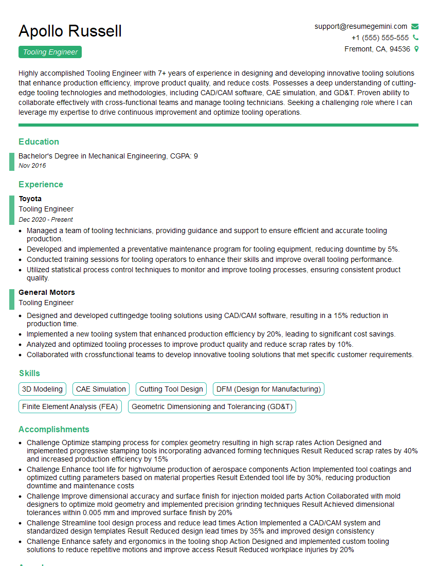
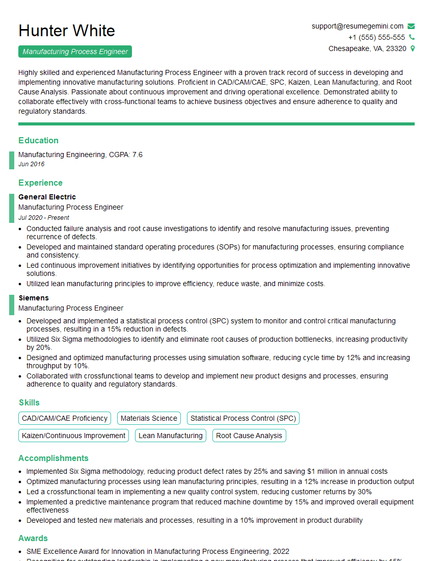
Mastering HyperMill or Mastercam is key to unlocking exciting career opportunities in manufacturing and design. Proficiency in these software packages significantly enhances your value to potential employers. To maximize your job prospects, create a compelling and ATS-friendly resume that showcases your skills effectively. ResumeGemini is a trusted resource to help you build a professional and impactful resume. They provide examples of resumes tailored to HyperMill and Mastercam users, ensuring your application stands out from the competition. Invest time in crafting a strong resume; it’s your first impression and a crucial step towards landing your dream job.
Explore more articles
Users Rating of Our Blogs
Share Your Experience
We value your feedback! Please rate our content and share your thoughts (optional).
What Readers Say About Our Blog
Hi, I’m Jay, we have a few potential clients that are interested in your services, thought you might be a good fit. I’d love to talk about the details, when do you have time to talk?
Best,
Jay
Founder | CEO
