The right preparation can turn an interview into an opportunity to showcase your expertise. This guide to Use precision measuring instruments and gauges interview questions is your ultimate resource, providing key insights and tips to help you ace your responses and stand out as a top candidate.
Questions Asked in Use precision measuring instruments and gauges Interview
Q 1. Explain the difference between accuracy and precision in measurement.
Accuracy and precision are often confused, but they represent different aspects of measurement quality. Accuracy refers to how close a measurement is to the true or accepted value. Think of it like aiming at a bullseye – a highly accurate measurement hits the center. Precision, on the other hand, refers to how close repeated measurements are to each other. It’s about consistency. Imagine shooting multiple arrows; high precision means all the arrows are clustered tightly together, regardless of whether they hit the bullseye. A measurement can be precise but not accurate (all arrows clustered, but off-target), accurate but not precise (arrows scattered, but the average is near the bullseye), or both accurate and precise (arrows clustered in the bullseye).
Example: Let’s say the true length of a metal rod is 10.00 cm. A series of measurements yielding 10.01, 10.02, and 10.00 cm demonstrates high precision (closely clustered measurements) but only moderate accuracy (slightly off the true value). Another set of measurements like 9.95, 10.05, and 10.10 cm shows low precision (widely scattered) and also low accuracy.
Q 2. Describe your experience with different types of micrometers (e.g., outside, inside, depth).
I have extensive experience with various micrometer types. Outside micrometers are used to measure the external dimensions of objects, like the diameter of a shaft or the thickness of a plate. I’m proficient in using both ratchet-type and plain micrometers, understanding the importance of proper anvil and spindle contact for precise measurements. Inside micrometers are designed for measuring internal dimensions, such as the diameter of a hole or bore. These often require extension rods to accommodate different sizes. My experience includes utilizing various rod lengths and ensuring proper alignment for accurate internal measurements. Lastly, depth micrometers measure the depth of a cavity, recess, or hole. I understand how critical it is to position the micrometer correctly to avoid inaccuracies due to angle.
In my previous role, I used micrometers daily to ensure components met the required tolerances in the manufacturing process. I’ve had to troubleshoot issues, such as identifying wear on the micrometer or ensuring proper zeroing before each measurement session. This hands-on experience has equipped me with a thorough understanding of their capabilities and limitations.
Q 3. How do you calibrate a vernier caliper?
Calibrating a vernier caliper involves ensuring its accuracy against a known standard. The process usually involves these steps:
- Clean the caliper: Remove any dirt or debris that could interfere with the measurement.
- Check the zero setting: Close the jaws completely. If the scales don’t align at zero, there is a zero error that needs to be accounted for in subsequent measurements. Some calipers have a zero adjustment mechanism to correct this.
- Compare against a standard gauge block: Use a set of known gauge blocks (precisely manufactured blocks with known dimensions) to verify the caliper’s accuracy at different points along its range. The difference between the gauge block’s known dimension and the caliper’s reading indicates any systematic error.
- Document the findings: Record any discrepancies and the correction needed for accurate measurements.
- Repeat as needed: Recheck calibration regularly to ensure accuracy.
Regular calibration is crucial for maintaining the vernier caliper’s accuracy, ensuring reliable measurements in quality control and manufacturing applications. Neglecting calibration can lead to costly mistakes.
Q 4. What are common sources of error when using precision measuring instruments?
Several factors can introduce errors when using precision measuring instruments. These include:
- Parallax error: This occurs when the observer’s eye is not positioned directly above the scale reading, leading to inaccurate readings. Proper eye positioning is crucial.
- Instrument wear: Over time, instruments can wear down, leading to inaccurate measurements. Regular maintenance and calibration are essential.
- Improper handling: Dropping or mishandling instruments can damage them, affecting accuracy.
- Temperature variations: Temperature changes can affect the dimensions of both the instrument and the object being measured, introducing thermal expansion errors.
- Improper clamping force: Applying too much or too little force when using instruments like micrometers can lead to inaccurate readings.
- Environmental factors: Dust, moisture, or vibrations can affect measurement accuracy.
Careful handling, regular calibration, and proper technique are essential to minimize these errors and achieve accurate and reliable measurements.
Q 5. Explain the principle of operation of a dial indicator.
A dial indicator, also known as a dial gauge, works on the principle of mechanical amplification. A small movement of a plunger or contact point is magnified by a gear system, which drives a pointer rotating around a dial. The dial is calibrated to display the magnified movement in precise units, typically in thousandths of an inch or millimeters. The amount of rotation of the pointer is directly proportional to the displacement of the plunger. This allows for highly sensitive measurements of small changes in dimension or position.
In simpler terms: Imagine a lever system – a small movement at one end results in a much larger movement at the other. The dial indicator uses a similar principle to amplify the tiny movements of the object being measured, making them easily visible and readable on the dial.
Q 6. How do you choose the appropriate measuring instrument for a specific task?
Selecting the right measuring instrument depends entirely on the task at hand. Consider these factors:
- Required accuracy: High-precision tasks require instruments like micrometers or vernier calipers; less precise tasks may only need a ruler or a tape measure.
- Size and shape of the object: Inside micrometers are needed for internal dimensions; outside micrometers for external; depth micrometers for depth measurements. For irregularly shaped objects, optical comparators or coordinate measuring machines (CMMs) might be necessary.
- Material of the object: Some materials might require specialized instruments.
- Measurement range: Choose an instrument with a measurement range that encompasses the object’s dimensions.
- Accessibility: Some areas might require specialized instruments, such as bore gauges for deep holes.
For instance, measuring the diameter of a precision shaft would require a micrometer, while measuring the length of a room would require a tape measure. Understanding these factors enables selecting the most suitable and efficient instrument for any given measurement task.
Q 7. Describe your experience with optical comparators.
Optical comparators are precision instruments used for comparing the shape and dimensions of an object to a projected master drawing or template. They project a magnified image of the object onto a screen, enabling precise visual inspection and measurement of features like profiles, angles, and dimensions. My experience involves operating both shadowgraph and profile projectors, understanding the importance of proper setup, lighting, and magnification selection to achieve accurate comparisons. I’m proficient in interpreting the projected image and identifying discrepancies between the object and the master drawing. This expertise is invaluable in quality control for ensuring parts conform to the design specifications.
In a previous project, I utilized an optical comparator to inspect the intricate details of a small electronic component. The magnification allowed for the detection of minute defects that would have been impossible to identify with conventional measurement tools. This highlights the power of optical comparators for detailed inspection and quality assurance in precision manufacturing.
Q 8. How do you interpret measurement data from a CMM (Coordinate Measuring Machine)?
Interpreting data from a CMM involves understanding its coordinate system and the software used for data acquisition and analysis. The CMM uses probes to measure points on a part, generating a point cloud. This point cloud is then used to create a digital representation of the part. The software then compares the measured data to the CAD model (if available) or to specified geometric tolerances.
For example, let’s say we’re measuring a cylindrical part. The CMM will collect numerous points along the cylinder’s surface. The software then calculates parameters like diameter, roundness, cylindricity, and straightness. Deviations from nominal values, displayed as numerical values and potentially graphical representations, indicate the part’s conformance to design specifications. It’s crucial to understand the CMM’s report, including statistical data like standard deviation, to assess the overall measurement accuracy and repeatability. Any significant deviations must be carefully analyzed for root cause identification.
Consider a situation where a part shows a larger-than-acceptable deviation in roundness. The CMM report might reveal the deviation’s location on the cylinder, indicating a potential problem with the machining process. This detailed information helps in pinpointing the defect and improving the manufacturing process.
Q 9. What are the different types of gauges and their applications?
Gauges are precision measuring instruments used for quick and accurate checks, often in-process or at the end of production. They come in various types, each with specific applications:
- Go/No-Go Gauges: These are simple gauges that quickly determine whether a part is within tolerance. A ‘go’ gauge passes through a feature only if the feature is at or above the minimum acceptable size. A ‘no-go’ gauge passes through a feature only if it is at or below the maximum acceptable size.
- Plug Gauges: Used for measuring internal diameters of cylindrical parts. These are very precise cylindrical plugs that check if the hole is within the specified tolerance.
- Ring Gauges: Used for measuring external diameters of cylindrical parts, with similar function to plug gauges, but checking external dimensions.
- Snap Gauges: These have two jaws—a go and a no-go—and use a simple ‘snap’ to indicate if the part is within tolerance. They provide a quick, easy method for measuring dimensions.
- Dial Indicators/Dial Gauges: These measure small changes in dimension, such as surface irregularities or deviations from a specified plane. They are highly sensitive and used to detect small variations.
- Thread Gauges: Used to check the accuracy of screw threads, including pitch, diameter and lead.
The choice of gauge depends on the part’s geometry, the required precision, and the volume of parts to be checked.
Q 10. Explain the concept of tolerance and its significance in precision measurement.
Tolerance in precision measurement defines the permissible variation in a dimension or characteristic. It’s the acceptable range of values around a nominal or target value. It’s expressed using plus/minus values or bilateral tolerances (e.g., ±0.01 mm). It indicates how much a measured dimension can deviate from the ideal dimension and still be considered acceptable. Tolerances are crucial to ensure the interchangeability and functionality of manufactured parts.
Consider a shaft that needs to fit into a hole. Both the shaft and the hole will have specific tolerance values. If the shaft’s diameter falls outside the acceptable tolerance range for the hole, the parts won’t fit correctly. It emphasizes that even slight deviations can render a part unusable. Without tolerances, maintaining consistency in manufacturing and ensuring proper assembly would be impossible.
The significance of tolerance lies in its effect on functionality and interchangeability. Tight tolerances mean higher precision and potentially higher cost, but it ensures better fit and performance. Looser tolerances lead to lower manufacturing cost but might compromise product quality or reliability. Defining the appropriate tolerance is crucial to balancing these trade-offs. For instance, aircraft parts demand far tighter tolerances than, say, toys, due to safety critical applications.
Q 11. How do you handle discrepancies between measurements taken with different instruments?
Discrepancies between measurements from different instruments require a systematic approach to identify the root cause. The first step is to verify the calibration status of all instruments. Are they traceable to national or international standards? Calibration certificates must be reviewed to ensure they are up-to-date and valid. Second, evaluate the measurement uncertainty associated with each instrument. Instruments have inherent limitations, and their stated accuracy must be considered.
Next, check the measurement methods used. Were the instruments used correctly and consistently? Were measurements repeated to verify accuracy and reduce random errors? If systematic errors are suspected, evaluate the environment—temperature, humidity, vibration, etc.—to see if these could explain the discrepancies. It’s also important to understand the specific limitations of each instrument. For instance, a micrometer might be unsuitable for measuring complex surface profiles, which might better be measured with a CMM.
For example, if a micrometer and a caliper show different readings for a simple cylindrical shaft, the discrepancy could be from using different techniques, calibration error, or even the operator’s skill. Careful analysis and testing are crucial to pinpointing the issue and making a well-informed decision on whether to keep or discard the measurements.
Q 12. Describe your experience with surface roughness measurement techniques.
Surface roughness measurement involves determining the texture of a surface, usually expressed as Ra (average roughness). I’ve worked extensively with several techniques, including stylus profilometry and optical methods.
Stylus Profilometry: A stylus traces the surface profile, generating a digital representation. The software then calculates various surface roughness parameters like Ra, Rz (maximum height), and Rt (total height). This method is very precise but can be slow, and the stylus can damage very delicate surfaces.
Optical Methods: These use techniques like confocal microscopy or interferometry to generate 3D surface profiles, offering non-contact measurement. These methods are often faster and less prone to damaging the surface. However, they might be limited in terms of the maximum roughness they can accurately measure.
In my experience, choosing the appropriate technique depends on factors like the material, surface finish, required accuracy and the overall budget. For instance, I used stylus profilometry for precise characterization of highly machined metal parts while optical methods were preferred for analyzing the surface of delicate polymer films to avoid scratching the surface.
Q 13. What are the safety precautions when using precision measuring instruments?
Safety is paramount when using precision measuring instruments. Here are some key precautions:
- Proper Training: Thorough training is essential to understand the instrument’s operation and limitations. Improper use can lead to inaccuracies and damage.
- Calibration: Regularly calibrated instruments ensure accuracy and reliability, which is vital for safety-critical applications.
- Cleanliness: Keep instruments clean and free from dirt and debris to avoid measurement errors and damage.
- Handling: Handle instruments carefully to prevent damage or injury. Never apply excessive force.
- Personal Protective Equipment (PPE): Appropriate PPE, such as safety glasses, should be worn where necessary, particularly when using sharp instruments like dial indicators.
- Environmental Conditions: Be aware of the environmental conditions and their effect on measurements and instrument performance. Extreme temperatures or humidity can impact accuracy.
- Disposal: Follow proper disposal procedures for broken or damaged instruments and avoid disposing of them unsafely.
Following these procedures not only protects the instruments but also ensures operator safety and reliable measurements.
Q 14. How do you document and record measurement data?
Documenting and recording measurement data is crucial for traceability, analysis, and quality control. A standardized approach ensures data integrity and facilitates data sharing. I typically use a combination of methods:
- Data Sheets: Pre-designed forms containing essential information such as part identification, date, time, instrument used, measurement values, operator’s initials, and any relevant observations.
- CMM Software: CMM software automatically generates detailed reports including all measured coordinates, calculated parameters, and statistical analysis.
- Spreadsheets: Data are often entered into spreadsheets for easier analysis and charting. This allows for quick statistical evaluation, trend analysis and identification of potential issues.
- Database Systems: Larger organizations might use database systems to manage and store measurement data, enabling better long-term data management and traceability.
Regardless of the method, proper labeling, clear identification of the part, and complete recording of all relevant information are vital to the integrity of the data. Maintaining meticulous records enables effective root cause analysis, process improvement, and quality assurance.
Q 15. How familiar are you with statistical process control (SPC) charts?
Statistical Process Control (SPC) charts are vital tools for monitoring and controlling manufacturing processes. They graphically display data over time, allowing us to identify trends, variations, and potential problems before they significantly impact product quality. I’m very familiar with various SPC charts, including:
- Control charts (X-bar and R charts, X-bar and s charts): These are used to monitor the central tendency and dispersion of a process. For example, I’ve used X-bar and R charts to track the diameter of machined parts, immediately spotting any shifts in the average diameter or an increase in variability.
- Individuals and Moving Range (I-MR) charts: Ideal when individual measurements are taken, these help monitor a process where subgroups aren’t practical.
- p-charts and np-charts: These charts track the proportion or number of nonconforming units in a sample, essential for quality control in mass production. For instance, I’ve used p-charts to monitor the defect rate in a printed circuit board assembly line.
My experience includes interpreting chart patterns (e.g., identifying shifts, trends, and out-of-control points), calculating control limits, and using the information to implement corrective actions to improve process capability. Understanding SPC charts ensures consistent product quality and minimizes waste.
Career Expert Tips:
- Ace those interviews! Prepare effectively by reviewing the Top 50 Most Common Interview Questions on ResumeGemini.
- Navigate your job search with confidence! Explore a wide range of Career Tips on ResumeGemini. Learn about common challenges and recommendations to overcome them.
- Craft the perfect resume! Master the Art of Resume Writing with ResumeGemini’s guide. Showcase your unique qualifications and achievements effectively.
- Don’t miss out on holiday savings! Build your dream resume with ResumeGemini’s ATS optimized templates.
Q 16. Describe your experience using different types of measuring software.
My experience encompasses a wide range of measuring software, from basic data acquisition systems to sophisticated CMM (Coordinate Measuring Machine) software packages. I’m proficient in using software that interfaces with various measuring instruments, including:
- Micrometer and caliper software: Simple software for data logging and basic statistical analysis from these instruments.
- CMM software (e.g., PC-DMIS, PolyWorks): This advanced software allows for complex part programming, measurement execution, and detailed reporting. I’ve used this extensively for inspecting complex geometries with high precision, generating detailed inspection reports with dimensional tolerances.
- Image analysis software: Used for analyzing images captured from optical comparators or microscopes, enabling precise measurements of small features.
- Laser scanning software: Software to process point cloud data acquired from laser scanners, allowing for reverse engineering and 3D model creation.
I’m also familiar with the use of data management software to store, organize and retrieve measurement data ensuring traceability and compliance. The ability to choose and effectively use the appropriate software is critical for optimizing measurement accuracy and efficiency.
Q 17. Explain the importance of proper instrument handling and maintenance.
Proper instrument handling and maintenance are paramount to ensuring measurement accuracy and instrument longevity. Neglecting these can lead to inaccurate measurements, costly rework, and instrument damage. My approach involves:
- Following manufacturer’s instructions: This includes proper calibration procedures, cleaning protocols, and storage recommendations.
- Regular calibration: Calibration ensures the instrument is providing accurate readings, using traceable standards to validate its performance. I always document calibration procedures and results.
- Careful handling: Avoiding drops, impacts, and excessive force protects the instrument from damage. For example, I always use anti-static wrist straps when handling sensitive electronic instruments to prevent electrostatic discharge.
- Thorough cleaning: Keeping the instrument clean and free of debris prevents contamination and maintains accuracy. The cleaning method varies depending on the instrument material and type of contamination.
- Preventative maintenance: Regularly checking for wear and tear, replacing worn parts, and lubricating moving components can extend the life and maintain the accuracy of the instrument.
A well-maintained instrument provides consistent, reliable measurements, reducing uncertainty and improving overall product quality.
Q 18. What are the limitations of different measuring instruments?
Every measuring instrument has its limitations, and understanding these is crucial for selecting the right tool for the job and interpreting results correctly. Some examples include:
- Resolution: The smallest increment a device can measure. A micrometer has higher resolution than a ruler. If a feature is smaller than the resolution, accurate measurement isn’t possible.
- Accuracy: The degree of closeness of measurements to the true value. Environmental factors (temperature, humidity) can affect accuracy.
- Repeatability: The ability of an instrument to give the same reading under the same conditions. Operator skill plays a role here.
- Linearity: The consistency of error across the measurement range. Some instruments might be more accurate in the mid-range and less so at the extremes.
- Environmental factors: Temperature, humidity, and vibrations can significantly impact measurement accuracy for many instruments.
For example, using a dial caliper to measure a very small feature might be inaccurate compared to using an optical comparator. Choosing the appropriate instrument and understanding its limitations are essential for obtaining reliable results.
Q 19. How do you troubleshoot problems encountered while using precision measuring instruments?
Troubleshooting problems with precision measuring instruments requires a systematic approach. My process involves:
- Identify the problem: Start by clearly defining the issue – is it an inaccurate reading, a malfunctioning component, or something else?
- Check the obvious: Begin by checking for simple things like proper calibration, correct instrument setup, and environmental factors.
- Verify calibration: Ensure the instrument is properly calibrated and within its specified tolerances. If not, recalibrate or send it for professional calibration.
- Inspect the instrument: Look for signs of damage, wear, or contamination. Clean the instrument as needed.
- Consult documentation: Review the instrument’s manual for troubleshooting guides and potential solutions.
- Test with known standards: Compare measurements against known standards to verify the accuracy of the instrument.
- Seek expert assistance: If the problem persists, consult with a qualified technician or the instrument’s manufacturer.
For example, if a micrometer consistently gives incorrect readings, I would first check its calibration, then examine it for any damage or contamination. If the issue persists after these checks, I would contact a metrology expert.
Q 20. Explain your understanding of GD&T (Geometric Dimensioning and Tolerancing).
Geometric Dimensioning and Tolerancing (GD&T) is a standardized system for defining and communicating engineering tolerances on drawings. It uses symbols and notations to specify the permissible variations in the form, orientation, location, and runout of features on a part. My understanding encompasses:
- Basic GD&T symbols: I’m proficient in using symbols for straightness, flatness, circularity, cylindricity, profile of a line, profile of a surface, position, orientation, runout, and form control. I understand the meaning and application of each symbol.
- Datums and datum reference frames: I understand how datums are established and used to control the location and orientation of features. This is vital for ensuring proper assembly and functionality.
- Tolerance zones: I can interpret and apply tolerance zones to define the permissible variations of features.
- Material Condition Modifiers (MCM): I understand how MCMs affect the interpretation of tolerances. This allows me to correctly interpret and measure parts according to the specified conditions (e.g., maximum material condition, least material condition).
Understanding GD&T is essential for accurate part inspection and manufacturing. Using GD&T ensures parts meet design specifications and function correctly within an assembly.
Q 21. Describe your experience with laser measurement systems.
My experience with laser measurement systems includes utilizing various types of laser scanners and sensors for both contact and non-contact measurements. This involves:
- Laser triangulation sensors: I’ve used these for high-speed, non-contact measurements of surface profiles and dimensions. For example, in a quality control setting, I used one to measure the thickness of thin films with high accuracy.
- Laser scanning systems: I have experience in operating and processing data from 3D laser scanners used for creating point clouds of complex parts for reverse engineering and inspection. This is particularly valuable for inspecting intricate parts with difficult-to-reach areas.
- Laser interferometers: These highly precise instruments measure distances and displacements with nanometer accuracy. I’ve used these in situations requiring extreme precision.
My experience extends to understanding the principles behind laser measurement, including the effects of environmental factors, sensor calibration, and data processing. Interpreting data from these systems and generating meaningful reports to ensure parts conform to engineering specifications is a key skill.
Q 22. How do you ensure traceability in your measurement processes?
Traceability in measurement ensures that all measurements can be linked back to a known and reliable standard. This is crucial for verifying the accuracy and reliability of our work. We achieve this through a system of calibrated instruments and documented procedures. Each instrument is calibrated against a traceable standard, often a national or international standard, and the calibration certificate records the date, results, and the identification of the instrument and the calibration laboratory. This creates a chain of custody, allowing us to trace the accuracy of any measurement back to its origin.
For example, our micrometer might be calibrated against a gauge block certified by NIST (National Institute of Standards and Technology). This gauge block itself is traceable to primary standards maintained by NIST. This ensures that our micrometer’s readings are consistently accurate and reliable.
- Regular Calibration: Instruments are calibrated at specified intervals based on their use and the required accuracy.
- Calibration Certificates: These certificates serve as proof of traceability, detailing the calibration process and results.
- Documented Procedures: Standard operating procedures ensure consistent calibration and measurement practices.
Q 23. What are your preferred methods for verifying the accuracy of measuring instruments?
Verifying the accuracy of measuring instruments involves comparing their readings to known standards. Several methods are employed, depending on the instrument’s type and the required precision.
- Calibration using traceable standards: This is the most common and reliable method. As discussed earlier, we use certified gauge blocks, master gauges, or other traceable standards to check the accuracy of our instruments.
- Comparison with a known good instrument: Sometimes we compare readings from the instrument in question with readings from a similarly calibrated instrument that is known to be accurate. This helps identify potential discrepancies.
- Internal checks: Certain instruments have built-in self-checking mechanisms. For example, some digital calipers include a function to test the zero point.
- Statistical process control (SPC): For high-volume measurements, SPC methods can help identify trends and deviations from expected values, indicating potential instrument inaccuracies.
Think of it like checking a kitchen scale with known weights. If the scale consistently shows incorrect weights for known standards, it’s clear that it needs recalibration.
Q 24. Describe a situation where you had to use precision measurement to solve a problem.
In one project, we were manufacturing a precision part for aerospace applications. The part had extremely tight tolerances – differences of just a few microns could render the part unusable. During production, we noticed a slight increase in rejection rates due to dimensional inconsistencies. Initial inspection suggested a problem with the manufacturing process. However, after carefully analyzing the data, we discovered a systematic error in our measurement process. A key measurement instrument – a high-precision CMM (Coordinate Measuring Machine) – had not been recently calibrated.
We immediately recalibrated the CMM using traceable standards and re-inspected the suspect parts. This revealed that the initial measurements were off by a few microns, leading to incorrect rejection decisions. Once the calibration was corrected, the rejection rates dropped significantly and the issue was resolved. The careful use of precision measurement tools and the systematic traceability of measurements was essential in identifying and resolving this problem.
Q 25. Explain your understanding of different units of measurement (e.g., inches, millimeters, microns).
Understanding different units of measurement is paramount in precision work. They represent different scales of size and precision:
- Inches (in): A common unit in some industries (e.g., aerospace, manufacturing). One inch is divided into fractions (e.g., 1/16, 1/32, 1/64) and decimals (e.g., 0.1 inch, 0.01 inch).
- Millimeters (mm): Part of the metric system, widely used internationally. One millimeter is 1/1000 of a meter.
- Microns (µm): Also known as micrometers, this unit is one millionth of a meter. It’s used for extremely precise measurements, common in microelectronics and nanotechnology. One micron is 1/1000 of a millimeter.
The relationship between these units is crucial for accurate conversion: 1 inch = 25.4 mm; 1 mm = 1000 µm. The ability to quickly and accurately convert between these units is vital for effective communication and problem-solving. Improper conversion can lead to significant errors, particularly with fine tolerances.
Q 26. How do you handle non-conforming parts based on your measurement results?
Handling non-conforming parts begins with a thorough investigation to determine the root cause of the non-conformance. This often involves re-measuring the part using different instruments or techniques to confirm the initial measurement. Based on the investigation, several actions may be taken:
- Rework: If the defect is minor and easily correctable, the part may be reworked to meet specifications.
- Scrap: If the defect is significant or cannot be economically corrected, the part is scrapped.
- Concession: In certain situations, a concession may be granted to use the non-conforming part, provided it meets specific criteria and the risks are assessed and accepted. This usually requires approval from the relevant authorities.
- Process Improvement: The root cause of the non-conformance is carefully analyzed and actions are taken to prevent recurrence. This might involve adjusting the manufacturing process, recalibrating instruments, or improving operator training.
Proper documentation of each step is crucial for maintaining quality control and traceability.
Q 27. What are some common types of measurement errors and how can they be avoided?
Measurement errors can significantly impact the accuracy and reliability of results. Some common types of errors include:
- Parallax Error: This occurs when the observer’s eye is not directly aligned with the measurement scale, leading to inaccurate readings. It’s common when using analog instruments like vernier calipers or micrometers.
- Calibration Error: An uncalibrated or poorly calibrated instrument will produce inaccurate results. Regular calibration is essential.
- Environmental Errors: Temperature, humidity, and vibration can all affect the accuracy of measurements. Maintaining stable environmental conditions is important.
- Operator Error: Human errors such as incorrect reading, misalignment, or improper handling of instruments can lead to mistakes. Proper training and adherence to standard procedures are vital.
- Systematic Errors: These are consistent errors that occur repeatedly. They can stem from instrument defects, incorrect instrument usage, or flaws in the measurement process.
- Random Errors: These are unpredictable errors that vary randomly. They can be minimized by repeating measurements and using statistical methods to analyze the data.
Avoiding these errors involves using calibrated instruments, following established procedures, performing regular checks, maintaining consistent environmental conditions, employing proper techniques, and utilizing statistical methods for data analysis. A combination of these strategies contributes to accurate and reliable measurements.
Key Topics to Learn for Precision Measuring Instruments and Gauges Interview
- Understanding Measurement Systems: Mastering the metric and imperial systems, including conversions and tolerances.
- Types of Measuring Instruments: Familiarizing yourself with calipers (vernier and digital), micrometers, dial indicators, height gauges, and their applications.
- Reading and Interpreting Measurements: Developing proficiency in accurately reading and recording measurements from various instruments, including understanding least count and precision.
- Practical Applications: Understanding how these instruments are used in quality control, manufacturing, machining, and inspection processes. Be prepared to discuss real-world scenarios where precision measurement is critical.
- Error Analysis and Calibration: Knowing how to identify and minimize sources of error in measurement, including instrument calibration and proper handling techniques.
- Troubleshooting and Problem Solving: Being able to diagnose issues with measurements, such as inconsistent readings or instrument malfunction.
- Safety Procedures: Understanding and adhering to safety regulations when using precision measuring instruments.
- Specific Gauge Types: Gaining familiarity with plug gauges, ring gauges, thread gauges, and other specialized gauges relevant to your target role.
- Data Recording and Documentation: Understanding best practices for accurately recording and documenting measurement data.
- Statistical Process Control (SPC): Basic understanding of SPC concepts and how they relate to precision measurement and quality control.
Next Steps
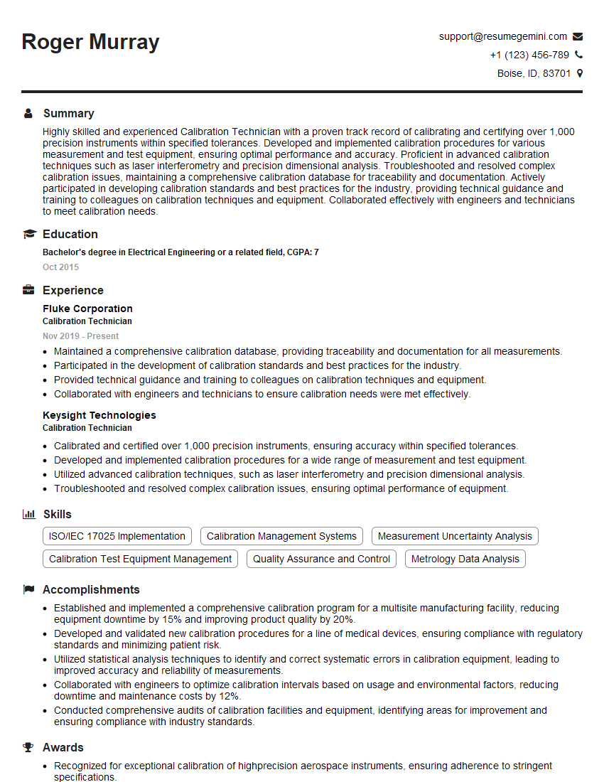
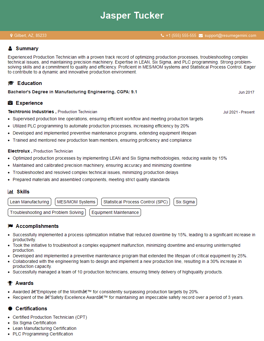
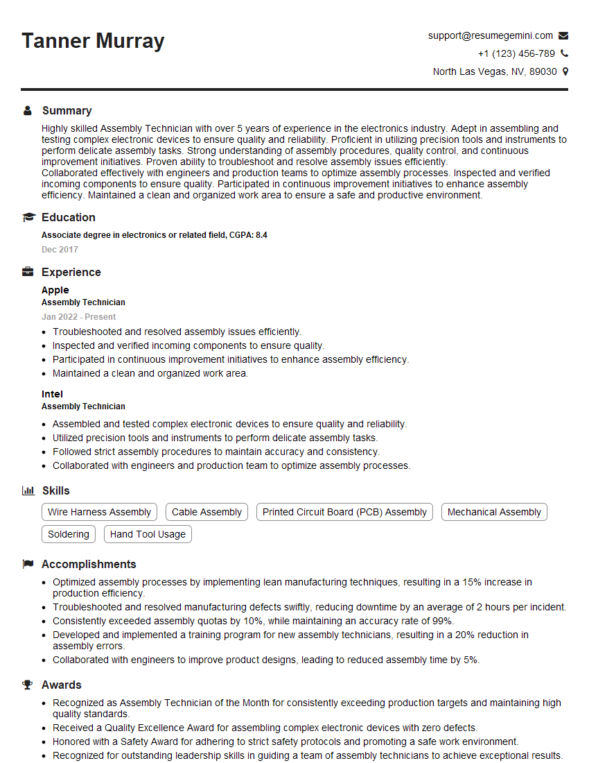
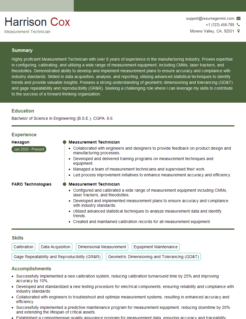
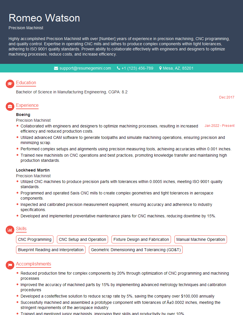
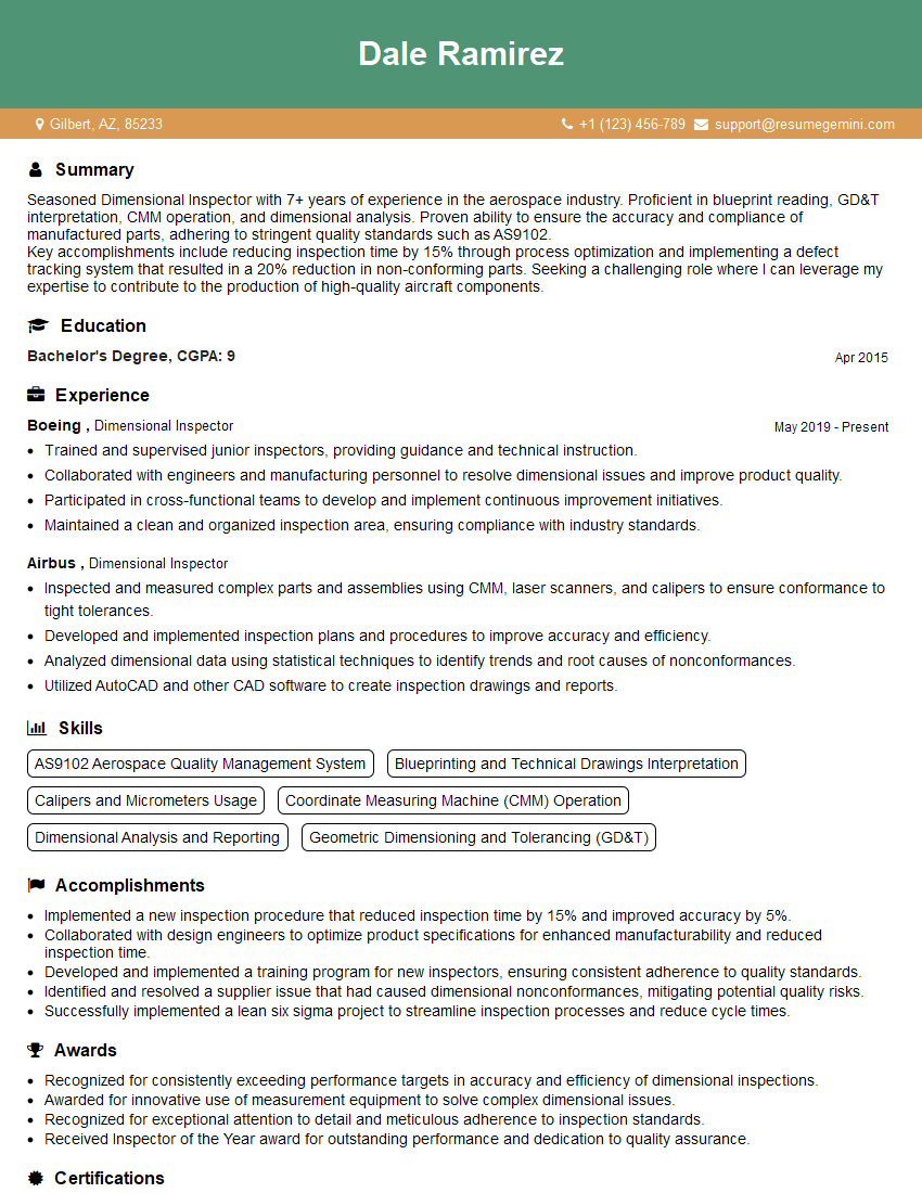
Mastering the use of precision measuring instruments and gauges is crucial for success in many high-demand technical fields. Proficiency in this area demonstrates attention to detail, problem-solving skills, and a commitment to quality – all highly valued attributes by employers. To significantly improve your job prospects, focus on crafting an ATS-friendly resume that highlights your skills and experience effectively. ResumeGemini is a trusted resource that can help you build a professional and impactful resume. We provide examples of resumes tailored to showcase experience in precision measuring instruments and gauges to help you get started.
Explore more articles
Users Rating of Our Blogs
Share Your Experience
We value your feedback! Please rate our content and share your thoughts (optional).
What Readers Say About Our Blog
Hi, I’m Jay, we have a few potential clients that are interested in your services, thought you might be a good fit. I’d love to talk about the details, when do you have time to talk?
Best,
Jay
Founder | CEO
