Preparation is the key to success in any interview. In this post, we’ll explore crucial Engineering Design and Analysis interview questions and equip you with strategies to craft impactful answers. Whether you’re a beginner or a pro, these tips will elevate your preparation.
Questions Asked in Engineering Design and Analysis Interview
Q 1. Explain the Finite Element Method (FEM) and its applications.
The Finite Element Method (FEM) is a powerful numerical technique used to analyze complex engineering problems. Imagine breaking a complex shape, like a car chassis, into many smaller, simpler shapes – these are the ‘finite elements’. We then apply known physical laws (like stress-strain relationships) to each element, solving a system of equations to approximate the overall behavior of the entire structure.
This allows us to predict things like stress, strain, displacement, and temperature under various loading conditions. It’s like solving a giant jigsaw puzzle, where each piece represents a small part of the larger system.
- Applications: FEM is widely used in various fields, including:
- Structural analysis: Designing bridges, buildings, and aircraft components.
- Fluid dynamics: Simulating airflow over an airplane wing or water flow in a pipe.
- Heat transfer: Analyzing temperature distributions in electronic components or engines.
- Electromagnetism: Modeling electromagnetic fields in motors or antennas.
For instance, in designing a bridge, FEM helps engineers determine the optimal size and material of the supporting beams to ensure the bridge can withstand expected loads without collapsing. It allows for iterative design improvements before physical prototypes are built, saving time and resources.
Q 2. Describe your experience with different CAD software (e.g., SolidWorks, AutoCAD).
I have extensive experience with several CAD software packages, including SolidWorks, AutoCAD, and CATIA. SolidWorks is my primary tool for 3D modeling and simulations, particularly for complex assemblies and detailed part design. Its intuitive interface and powerful simulation capabilities are invaluable for creating accurate models and performing stress analysis.
AutoCAD, on the other hand, is excellent for 2D drafting and detailed drawings needed for manufacturing. I use it frequently for creating technical drawings, schematics, and detailed documentation. My experience with CATIA comes from working on aerospace projects where its surface modeling capabilities were critical for aerodynamic design optimization.
In one project, I used SolidWorks to model a complex robotic arm, generating detailed drawings for manufacturing in AutoCAD. The FEM analysis within SolidWorks helped optimize the arm’s design for strength and weight, ensuring it could withstand the stresses of its intended operation.
Q 3. How do you perform a stress analysis on a complex component?
Performing stress analysis on a complex component involves a systematic approach. It begins with creating a realistic 3D model of the component using CAD software. Then, I define the material properties, boundary conditions (how the component is supported), and applied loads (forces and pressures). This is akin to setting the stage for an experiment.
Next, I use FEM software (like ANSYS or Abaqus) to mesh the model, dividing it into numerous finite elements. The finer the mesh, the more accurate the results, but it also increases computation time. The software then solves the governing equations to determine the stress and strain distribution throughout the component.
Finally, I review the results, focusing on areas of high stress concentration. I check if these stresses are within the allowable limits for the chosen material. If not, I iterate on the design, modifying geometry or material properties until the stress levels are acceptable. For instance, I might add reinforcement to areas of high stress or explore using a stronger material. This process involves careful consideration of safety factors and relevant design codes.
Q 4. What are the different types of failure modes you have encountered?
During my career, I’ve encountered several failure modes, each requiring a unique approach to prevention and mitigation. These include:
- Yielding: The material deforms plastically beyond its elastic limit. This often manifests as permanent deformation. For example, a bent metal beam that doesn’t return to its original shape.
- Fracture: Complete separation of the material due to excessive stress. This can be brittle (sudden and catastrophic) or ductile (with some plastic deformation before failure).
- Fatigue: Failure due to repeated cyclic loading, even if the stress levels are below the yield strength. This is like repeatedly bending a paperclip until it breaks.
- Buckling: Sudden collapse of a slender member under compressive load. Think of a long, thin column bending under its own weight.
- Creep: Time-dependent deformation under sustained stress at elevated temperatures. This is common in high-temperature applications like turbine blades.
Understanding these failure modes is critical for designing robust and reliable components.
Q 5. Explain your experience with fatigue analysis.
Fatigue analysis is crucial for components subjected to cyclic loading, where failure may occur at stress levels far below the yield strength. My experience in fatigue analysis involves using specialized software and applying various methods to predict the fatigue life of components.
The process starts with identifying the loading spectrum – the range and frequency of cyclic stresses. Then, I utilize various fatigue analysis techniques, such as:
- S-N curves: These curves relate the stress amplitude to the number of cycles to failure for a given material.
- Strain-life methods: These consider the plastic strain component to better predict fatigue life at higher stress levels.
- Fracture mechanics: This approach examines crack propagation to predict fatigue life accurately.
For example, in designing an aircraft wing, fatigue analysis is critical to ensure the wing can withstand thousands of flight cycles without fracturing. This involves sophisticated simulations and careful consideration of various load cases, including gusts and maneuvers.
Q 6. How do you handle design changes during a project?
Handling design changes during a project requires a structured and collaborative approach. First, any proposed change must be documented, clearly stating the reason for the modification and its potential impact on other aspects of the design. This is essential for maintaining traceability and avoiding unintended consequences.
Next, a thorough impact assessment is conducted. This involves evaluating how the change affects: functionality, performance, cost, and schedule. A design review meeting with relevant stakeholders – engineers, managers, and potentially clients – then takes place to evaluate the merits of the change.
If approved, the design is updated, and any necessary documentation is revised. Version control is critical here to track changes and facilitate reverting to previous versions if needed. Thorough testing and validation of the updated design are carried out to ensure the change hasn’t introduced any new problems.
Q 7. Describe your process for verifying and validating a design.
Verification and validation (V&V) are essential to ensure a design meets its requirements and performs as intended. Verification focuses on confirming that the design meets its specifications, while validation focuses on confirming that the design meets the user’s needs and expectations.
My V&V process typically involves:
- Requirements Traceability: Ensuring that all design aspects are traceable back to the initial requirements.
- Design Reviews: Conducting formal reviews at various design stages to identify and address potential issues.
- Analysis and Simulation: Using FEM and other simulation techniques to assess design performance.
- Prototyping and Testing: Creating physical prototypes and conducting testing to validate design performance under various conditions.
- Documentation: Maintaining comprehensive documentation throughout the process.
For example, after designing a new engine component, I would verify that the component meets the specified strength and weight requirements through analysis. I would then validate that the component performs reliably in a real-world engine environment through testing on a prototype engine.
Q 8. How do you balance design requirements with manufacturing constraints?
Balancing design requirements with manufacturing constraints is a crucial aspect of successful engineering. It’s essentially a negotiation between what’s ideally desired and what’s realistically feasible to produce. This involves a constant iterative process of refinement.
The process usually begins with a thorough understanding of both sides. Design requirements often stem from performance needs, customer specifications, or regulatory compliance. These could include things like strength, weight, size, and functionality. Manufacturing constraints, on the other hand, are limitations imposed by the production process, materials availability, tooling capabilities, and cost considerations. These might include limitations on material thickness, achievable tolerances, available machinery, and production volume.
A common approach involves using Design for Manufacturing (DFM) principles (discussed further in question 7). This involves early collaboration with manufacturing engineers to identify potential problems and make design changes early in the process. Techniques like Design of Experiments (DOE) can also be used to systematically explore the design space and find optimal solutions that meet both requirements and constraints. For example, if a design requires a very tight tolerance on a specific dimension, we might need to assess whether this is actually necessary or if a slightly looser tolerance would be acceptable while still meeting functional requirements and significantly reducing manufacturing cost and complexity.
Ultimately, successful balancing often involves trade-offs. Sometimes, compromises must be made to achieve a functional and manufacturable product. This might involve selecting a different material, simplifying geometry, or modifying the assembly process. Prioritization and risk assessment are critical components of this process.
Q 9. Explain your experience with tolerance analysis.
Tolerance analysis is a critical part of engineering design, ensuring that parts fit together and function as intended. It involves quantifying and propagating the uncertainties in dimensions and other parameters throughout the design process.
My experience includes using both statistical and worst-case tolerance analyses. Statistical tolerance analysis uses statistical distributions to model variations in dimensions and calculates the probability of assembly issues. This approach is beneficial when dealing with large numbers of parts and when slight variations are acceptable. Worst-case analysis assumes the maximum possible deviation in each dimension and assesses the resulting impact on the assembled product. This approach is more conservative and suitable for safety-critical applications where failures cannot be tolerated. I have used software tools such as Tolerance Analysis software (e.g. 3DCS, CETOL) to automate these analyses.
For example, in designing a complex assembly like an engine, I’ve used tolerance analysis to ensure that the piston and cylinder bore have sufficient clearance without causing excessive play or interference. Proper tolerance stack-up analysis helped prevent potential issues such as piston seizure or excessive wear. In other projects, tolerance analysis has been crucial in determining the required precision of machined components to ensure assembly functionality while minimizing manufacturing costs.
Q 10. How do you perform a thermal analysis?
Thermal analysis involves determining the temperature distribution and heat transfer within a system or component. This is crucial for ensuring that a design can withstand expected thermal loads without malfunction or damage. The process usually involves these steps:
- Defining the problem: This includes identifying the heat sources, boundary conditions (temperatures, heat fluxes), and material properties.
- Choosing a method: This can range from simple hand calculations for basic geometries to sophisticated Finite Element Analysis (FEA) simulations for complex designs. FEA uses numerical techniques to solve the heat equation and determine the temperature field.
- Creating a model: This involves creating a geometric model of the system, defining material properties, and specifying boundary conditions. Software packages such as ANSYS, Abaqus, or COMSOL are often employed for this step.
- Performing the simulation: The FEA software solves the heat equation numerically to obtain the temperature distribution.
- Post-processing and interpretation: This involves visualizing the results (temperature contours, heat fluxes), identifying potential hot spots or thermal stresses, and assessing whether the design meets the required thermal criteria.
For instance, in designing a heat sink for an electronic device, I’ve used thermal analysis to ensure that the component’s temperature remains below its maximum operating temperature under various operating conditions. The analysis helps optimize the heat sink design (fin geometry, material selection) to effectively dissipate heat.
Q 11. What are your experiences with CFD simulations?
Computational Fluid Dynamics (CFD) simulations are used to model and analyze fluid flow and heat transfer. My experience involves utilizing CFD software (like ANSYS Fluent, OpenFOAM) to solve Navier-Stokes equations and predict fluid behavior in various applications.
I’ve used CFD for tasks such as aerodynamic analysis of vehicle components to reduce drag, optimize the design of internal flow passages in heat exchangers to enhance efficiency, and analyzing the flow patterns around building structures to assess wind loading. The process usually involves creating a geometric model of the fluid domain, defining boundary conditions (inlet/outlet velocities, pressures, temperatures), selecting appropriate turbulence models, and solving the governing equations. Post-processing then allows for visualization of flow patterns, pressure distributions, velocity profiles, and other relevant quantities.
For example, in a project involving the design of a cooling fan for a server rack, I used CFD to optimize the fan blade geometry and housing design to maximize airflow and minimize noise. The simulations helped identify areas of recirculation or flow separation that could be improved through design modifications. The results of the CFD analysis were then used to guide the design iterations and ensure that the cooling system met the specified performance requirements.
Q 12. Describe a time you had to troubleshoot a design problem.
During the development of a robotic arm, we encountered a problem where the arm’s end-effector (the part that interacts with the environment) experienced excessive vibration at certain speeds. This was unacceptable because it affected the precision of the arm’s movements.
Our troubleshooting process began with careful observation and data collection. We measured the vibrations using accelerometers, and analyzed the data to identify the frequency and amplitude of the vibrations. This pointed to resonance as the likely cause. We then conducted a modal analysis using FEA software to determine the natural frequencies of the arm structure. This revealed that one of the arm’s natural frequencies was very close to the operating frequency, leading to resonance and amplified vibrations.
To solve the problem, we explored several options. We considered modifying the arm’s geometry to shift its natural frequencies away from the operating range, adding damping materials to reduce vibration, or adjusting the control system to avoid exciting the resonant frequency. After evaluating the trade-offs between cost, complexity, and performance, we opted to add a small amount of damping material at strategic locations on the arm. This effectively reduced the vibrations to an acceptable level, successfully resolving the issue.
Q 13. How do you prioritize design features when faced with limitations?
Prioritizing design features under limitations requires a systematic approach. The process generally involves:
- Identifying critical features: This involves determining which features are essential for the product’s core functionality and safety. These should be prioritized above all others.
- Analyzing feature importance: This involves assessing the relative importance of each feature based on factors such as customer needs, market demands, and regulatory compliance.
- Assessing feasibility and cost: This involves evaluating the technical feasibility and cost implications of implementing each feature, considering manufacturing constraints and resource limitations.
- Creating a weighted matrix: This combines importance and feasibility to create a prioritized list of features. This might involve assigning weights to each factor and calculating a weighted score for each feature.
- Iterative refinement: This involves reassessing priorities as design progresses, considering new insights and trade-offs.
For example, in designing a new smartphone, the essential features (processor, battery, screen) will always take priority over less critical features (camera resolution, specific app integration). If resource constraints exist, we might prioritize improving the battery life over adding a higher-resolution camera, based on market research suggesting battery life is a more significant customer concern.
Q 14. Explain your understanding of design for manufacturing (DFM).
Design for Manufacturing (DFM) is a crucial approach to engineering design that focuses on optimizing the design of a product to improve its manufacturability, reduce costs, and ensure quality. It involves considering the manufacturing process from the outset of the design phase, rather than as an afterthought.
DFM encompasses a wide range of considerations, including:
- Material selection: Choosing materials that are readily available, easy to process, and cost-effective.
- Geometric simplification: Avoiding complex geometries that are difficult and expensive to manufacture.
- Tolerance analysis: Ensuring that tolerances are achievable and cost-effective.
- Assembly considerations: Designing parts that are easy to assemble and minimizing the number of parts.
- Manufacturing process selection: Selecting appropriate manufacturing processes (casting, machining, molding, etc.) that are suitable for the design and production volume.
- Tooling considerations: Considering the design of the required tooling, jigs, and fixtures.
By integrating DFM principles throughout the design process, engineers can reduce manufacturing costs, improve product quality, shorten lead times, and enhance overall product competitiveness. For example, designing a part with simple, symmetrical shapes can significantly reduce machining time and costs compared to using complex, intricate geometries. Similarly, selecting a readily available material rather than a specialized or exotic material can decrease both cost and lead time.
Q 15. How do you incorporate sustainability considerations into your designs?
Sustainability is paramount in modern engineering. It’s not just an add-on; it’s integrated into every stage of the design process, from initial concept to disposal. I approach it through a lifecycle assessment, considering the environmental impact of a product throughout its entire life – from material extraction and manufacturing to use and eventual recycling or disposal.
- Material Selection: I prioritize using recycled materials, bio-based materials, and materials with low embodied energy (the energy used to produce and transport the material). For example, choosing sustainably harvested timber over steel for certain structural elements can significantly reduce the carbon footprint.
- Design for Manufacturing: Minimizing waste during production is crucial. This involves optimizing designs for efficient manufacturing processes, reducing material usage, and designing for easy disassembly and component reuse at the end of the product’s life.
- Design for Disassembly: Products should be designed to be easily taken apart for repair, reuse, or recycling. This reduces landfill waste and allows for the recovery of valuable materials. For example, modular designs where components can be replaced individually, rather than replacing the entire product, are a great example.
- Energy Efficiency: Incorporating energy-efficient components and systems into designs is critical. This might involve using energy-efficient motors, improving insulation in buildings, or designing for passive solar heating and cooling.
Ultimately, sustainable design is about minimizing the negative environmental impact and maximizing the positive social and economic benefits throughout the product’s entire life cycle.
Career Expert Tips:
- Ace those interviews! Prepare effectively by reviewing the Top 50 Most Common Interview Questions on ResumeGemini.
- Navigate your job search with confidence! Explore a wide range of Career Tips on ResumeGemini. Learn about common challenges and recommendations to overcome them.
- Craft the perfect resume! Master the Art of Resume Writing with ResumeGemini’s guide. Showcase your unique qualifications and achievements effectively.
- Don’t miss out on holiday savings! Build your dream resume with ResumeGemini’s ATS optimized templates.
Q 16. What is your experience with different materials and their properties?
My experience with materials is extensive, encompassing metals (steel, aluminum, titanium), polymers (plastics, composites), ceramics, and natural materials (wood, bamboo). Understanding material properties – strength, stiffness, ductility, density, thermal conductivity, and cost – is crucial for making informed design choices.
For example, in a recent project designing a lightweight drone chassis, I compared aluminum alloys and carbon fiber composites. Aluminum offered good strength-to-weight ratio and ease of machining, while carbon fiber provided superior strength and stiffness but was more expensive and challenging to manufacture. The final selection involved a trade-off based on performance requirements, cost constraints, and manufacturability.
I’m also experienced in using material databases and software like CES EduPack to assess material properties and make informed decisions. This allows for quick comparison of different options and avoids costly mistakes during the design stage.
Q 17. Describe your experience with design reviews and feedback.
Design reviews are an essential part of my workflow. I actively seek feedback to ensure designs meet requirements and are optimized for performance, manufacturability, and cost. I’ve participated in numerous design reviews, both as a presenter and a reviewer.
- Presenting: I prepare clear and concise presentations, using visuals to effectively communicate design concepts and analysis results. I anticipate potential questions and concerns and address them proactively.
- Reviewing: I approach reviews critically, evaluating designs from multiple perspectives, including functionality, safety, manufacturability, and sustainability. I offer constructive feedback focusing on solutions rather than solely pointing out problems.
Feedback is incorporated iteratively into designs. I use feedback to refine designs and address any identified shortcomings. This collaborative approach is key to developing high-quality, robust, and reliable designs. A recent bridge design project benefited greatly from a peer review that highlighted potential stress concentration areas I had overlooked.
Q 18. How do you ensure the accuracy of your analysis results?
Ensuring accuracy in analysis results is paramount. My approach involves a multi-pronged strategy:
- Validation of Models: I verify the accuracy of my models by comparing simulation results with experimental data whenever possible. If experimental data is unavailable, I might use simplified analytical models for comparison or leverage existing validated models from literature.
- Mesh Refinement (FEA): In finite element analysis (FEA), mesh density greatly influences accuracy. I use mesh convergence studies to ensure results are independent of the mesh size. This involves running the analysis with increasingly finer meshes until the results stabilize.
- Verification of Software: I use reputable and validated simulation software and regularly check for updates and ensure the software is correctly configured. I also employ verification techniques to confirm that the software is correctly implementing the underlying equations and algorithms.
- Multiple Analysis Techniques: When possible, I employ multiple analysis techniques to cross-validate results. For example, comparing results from FEA with hand calculations or using different FEA solvers.
- Peer Review: I encourage peer reviews of analysis results to identify potential errors or biases.
Accuracy is not just about getting the right numbers; it’s about understanding the limitations of the analysis and interpreting the results appropriately.
Q 19. Explain your experience with data analysis and interpretation.
Data analysis and interpretation are integral to my design process. I routinely use statistical methods, data visualization, and programming (Python, MATLAB) to analyze data from experiments, simulations, and field measurements.
For example, in optimizing the design of a wind turbine blade, I used experimental data from wind tunnel testing to create a statistical model relating blade geometry to aerodynamic performance. This allowed me to identify optimal blade shapes for maximum energy capture. Data visualization using plots and charts allowed for easy interpretation of complex datasets.
I’m proficient in using statistical software (e.g., Minitab) to perform regression analysis, ANOVA, and other statistical techniques to identify trends, correlations, and significant factors affecting design performance.
Q 20. How do you use simulation software to optimize designs?
Simulation software is invaluable for optimizing designs. I routinely use software such as ANSYS, Abaqus, and COMSOL for FEA, CFD (Computational Fluid Dynamics), and other simulations. Optimization involves systematically varying design parameters to find the best combination that meets performance requirements while minimizing cost and weight.
Example: In designing a pressure vessel, I used FEA to analyze stress and strain under various loading conditions. Then, I employed optimization algorithms within the FEA software to automatically adjust wall thickness while ensuring stress levels remained below allowable limits. This resulted in a lighter, more cost-effective design that met safety requirements. I also use Design of Experiments (DOE) methodologies to efficiently explore the design space and identify optimal parameter combinations.
Q 21. Describe a challenging design project you’ve worked on and how you overcame it.
One challenging project involved designing a lightweight yet robust support structure for a large solar panel array in a remote location. The challenges included minimizing weight for transportation and installation, withstanding high wind loads, and withstanding significant thermal stresses due to fluctuating temperatures.
My approach involved a combination of FEA, CFD, and material selection optimization. Initially, I used FEA to model the structural response of different designs to wind loads. CFD simulations were employed to accurately model wind flow around the structure. I explored different materials (aluminum alloys, carbon fiber composites) and design topologies (lattice structures, truss structures) to optimize the structure for weight and strength.
The iterative process involved multiple design revisions and refinements based on simulation results. The project ultimately required developing a novel lattice structure with optimized member sizes and configurations. Successful completion involved close collaboration with the manufacturing team to ensure the design was manufacturable and cost-effective.
Q 22. What are your strengths and weaknesses as a design engineer?
My greatest strength as a design engineer lies in my ability to blend creative problem-solving with rigorous analytical skills. I excel at translating complex engineering challenges into practical, manufacturable solutions. For example, during my previous role at XYZ Corporation, I was tasked with designing a more efficient cooling system for a high-performance server. By utilizing computational fluid dynamics (CFD) analysis and incorporating innovative heat sink designs, I reduced operating temperatures by 15%, significantly improving performance and extending the lifespan of the product.
However, I recognize that perfection is a continuous journey, and my area for development is delegation. While I’m highly detail-oriented, sometimes I find it challenging to trust others with aspects of a project, leading to unnecessary workload on my end. I’m actively addressing this through improved project management techniques and actively seeking opportunities to mentor junior engineers.
Q 23. How do you stay updated with the latest design and analysis techniques?
Staying current in the rapidly evolving field of engineering design and analysis requires a multi-pronged approach. I regularly attend industry conferences like ASME and SAE events to learn about the latest breakthroughs and network with peers. Additionally, I actively participate in online communities and forums, such as those hosted by professional engineering societies. This provides valuable exposure to real-world case studies and insightful discussions. I also subscribe to several leading engineering journals and publications, including Machine Design and Mechanical Engineering, to remain abreast of the latest research and advancements. Finally, I leverage online learning platforms like Coursera and edX to pursue specialized courses in areas like advanced FEA techniques or additive manufacturing processes.
Q 24. Explain your experience with different design methodologies (e.g., Agile, Waterfall).
My experience spans both Agile and Waterfall methodologies, and I’ve found that each has its place depending on the project’s specifics. In my early career, I worked predominantly on projects following the Waterfall methodology, which was well-suited for the highly structured and well-defined requirements of large-scale infrastructure projects. This approach provided a clear roadmap and ensured meticulous documentation. However, I’ve found that Agile methodologies are increasingly better suited for projects that require adaptability and quick iterations, particularly in software-integrated hardware design. For instance, in my recent project involving the design of a smart home automation system, the Agile approach allowed us to incorporate user feedback efficiently throughout the development cycle, resulting in a more user-friendly and robust final product. I’m adept at navigating both frameworks and selecting the most appropriate approach based on the project constraints and deliverables.
Q 25. How do you communicate technical information to non-technical audiences?
Communicating complex technical information to non-technical audiences is a critical skill for any engineer. My approach hinges on simplifying technical jargon and employing clear, concise language. I often use analogies and visual aids, such as diagrams, charts, and even physical models, to make abstract concepts more accessible. For example, when explaining the stress analysis of a bridge to a city council, I would avoid terms like ‘principal stress’ and instead focus on describing the forces acting on the bridge and how the design ensures its stability in plain language. I find that storytelling can be incredibly effective as well; weaving technical facts into a narrative helps maintain audience engagement and comprehension. I always aim for clarity and ensure that the audience can understand the key takeaways and implications of the information presented.
Q 26. What are your salary expectations?
My salary expectations are commensurate with my experience and skills, and align with the industry standard for a senior design engineer with my background. I’m open to discussing a competitive compensation package that fairly reflects my contributions and aligns with the company’s compensation structure.
Q 27. What are your long-term career goals?
My long-term career goals center around technical leadership and innovation. I envision myself in a role where I can mentor and guide younger engineers, fostering a collaborative and high-performing team. I’m also passionate about pushing the boundaries of engineering design by exploring and implementing cutting-edge technologies, particularly in sustainable and eco-friendly solutions. My ambition is to contribute significantly to the development of innovative products and solutions that positively impact society and the environment.
Q 28. Do you have any questions for me?
I’d like to learn more about the specific challenges and opportunities this role presents. I’m particularly interested in understanding the company’s approach to innovation and professional development, as well as the team dynamics and collaboration culture. Could you also tell me more about the specific technologies and tools used within the team, and the opportunities for professional growth and advancement within the company?
Key Topics to Learn for Engineering Design and Analysis Interview
- Design Principles and Methodologies: Understand fundamental design principles like functionality, aesthetics, manufacturability, and sustainability. Explore various design methodologies such as Design Thinking, Agile, and Lean.
- Material Selection and Properties: Learn how to select appropriate materials based on their mechanical, thermal, and chemical properties. Understand stress-strain relationships and failure theories.
- Finite Element Analysis (FEA): Grasp the fundamentals of FEA and its applications in structural analysis, heat transfer, and fluid dynamics. Be prepared to discuss meshing techniques and interpretation of results.
- Computational Fluid Dynamics (CFD): Familiarize yourself with the basics of CFD and its use in analyzing fluid flow and heat transfer in engineering systems. Understand different turbulence models and boundary conditions.
- Stress Analysis and Failure Prediction: Master concepts like stress concentration, fatigue analysis, and fracture mechanics. Be able to apply these concepts to real-world engineering problems.
- Experimental Design and Data Analysis: Understand the principles of experimental design, data acquisition, and statistical analysis for validating design decisions and drawing meaningful conclusions from experimental data.
- Technical Communication and Problem-Solving: Practice clearly articulating your design process, analysis methods, and conclusions. Develop strong problem-solving skills and the ability to think critically.
Next Steps
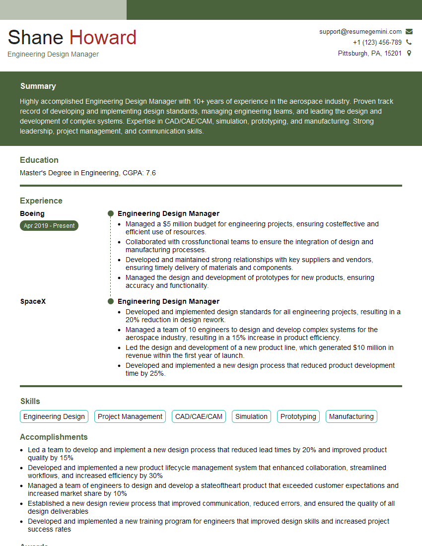
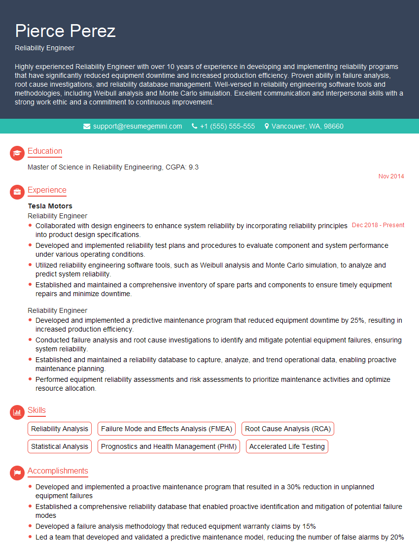
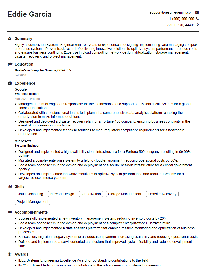
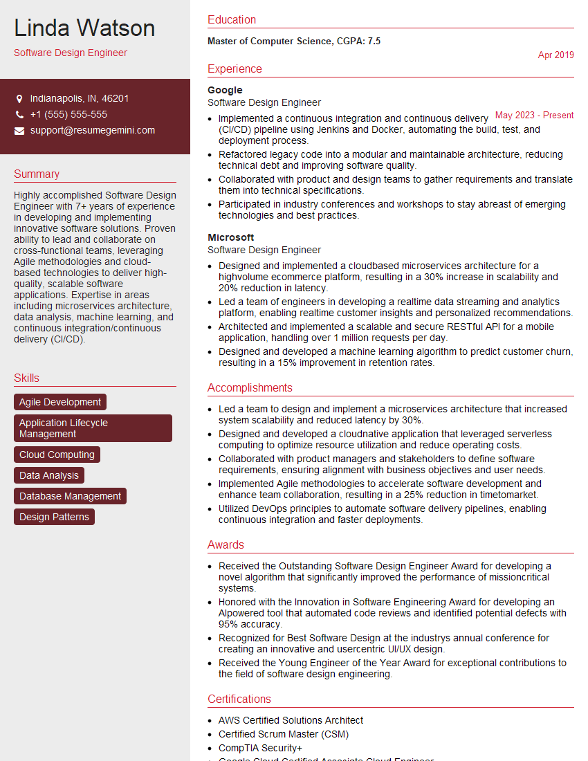
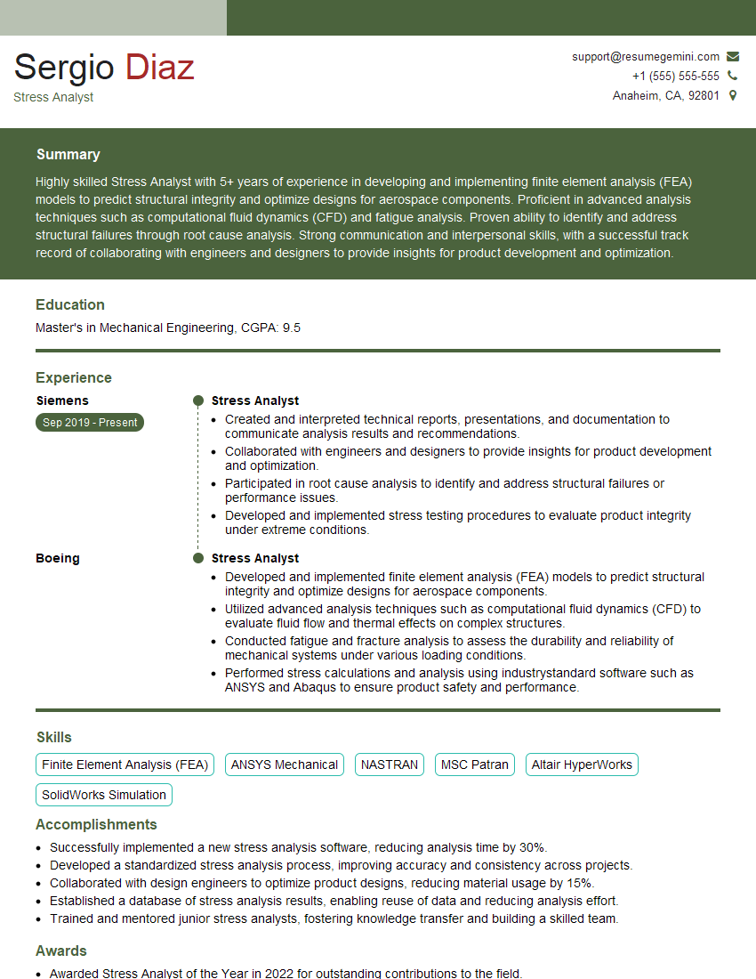
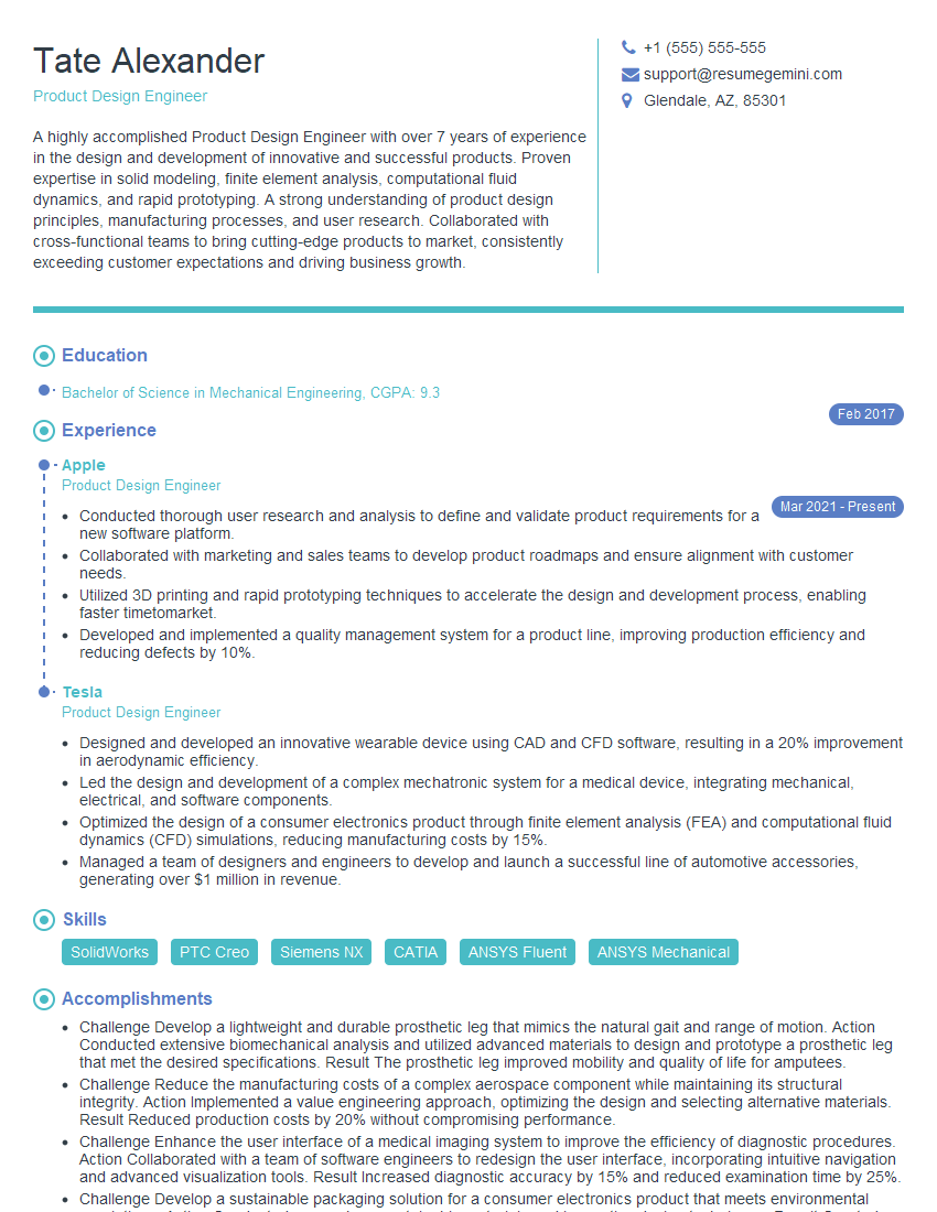
Mastering Engineering Design and Analysis opens doors to exciting and challenging careers with significant growth potential. To maximize your job prospects, creating a strong, ATS-friendly resume is crucial. ResumeGemini can help you build a professional and impactful resume tailored to your skills and experience. We offer examples of resumes specifically designed for candidates in Engineering Design and Analysis to guide you. Take the next step towards your dream career – build your best resume with ResumeGemini!
Explore more articles
Users Rating of Our Blogs
Share Your Experience
We value your feedback! Please rate our content and share your thoughts (optional).
What Readers Say About Our Blog
Hi, I’m Jay, we have a few potential clients that are interested in your services, thought you might be a good fit. I’d love to talk about the details, when do you have time to talk?
Best,
Jay
Founder | CEO
