Unlock your full potential by mastering the most common Fiber Patching interview questions. This blog offers a deep dive into the critical topics, ensuring you’re not only prepared to answer but to excel. With these insights, you’ll approach your interview with clarity and confidence.
Questions Asked in Fiber Patching Interview
Q 1. Explain the different types of fiber optic connectors.
Fiber optic connectors are the crucial interface between fiber optic cables and equipment. Several types exist, each with its strengths and weaknesses. Choosing the right connector is critical for reliable signal transmission.
- SC (Subscriber Connector): A popular choice known for its simplicity and robustness. It’s a push-pull connector, making it easy to connect and disconnect.
- FC (Ferrule Connector): Uses a threaded coupling mechanism, offering superior durability and repeatability. It’s often used in demanding environments.
- LC (Lucent Connector): A smaller, more compact connector that’s becoming increasingly popular due to its space-saving design and high density in patch panels.
- ST (Straight Tip Connector): A bayonet-style connector, known for its easy push-and-twist connection. However, it’s less common now compared to LC and SC.
- MT-RJ (Mechanical Transfer-Registered Jack): A dual-fiber connector, often used in telecommunications applications for increased bandwidth efficiency.
The selection of a specific connector type often depends on the application, budget, and space constraints. For instance, LC connectors are prevalent in data centers due to their high density, while SC connectors might be preferred in less dense deployments for their reliability.
Q 2. Describe the process of terminating a fiber optic cable.
Terminating a fiber optic cable is a precise process requiring careful attention to detail. Improper termination can result in signal loss, attenuation, and connection failure. Here’s a simplified process:
- Prepare the cable: Strip the outer jacket and cladding to the required length, taking care not to damage the fiber.
- Clean the fiber: Use appropriate cleaning materials (e.g., fiber optic cleaning wipes, pens) to remove any dust or debris from the fiber end. This is crucial for proper connection.
- Cleaving the fiber: Create a perfectly perpendicular cleave using a cleaver to ensure optimal light transmission. A poorly cleaved fiber leads to significant signal loss.
- Prepare the connector: Insert the prepared fiber end into the connector ferrule, ensuring it’s correctly positioned and free of air gaps. The adhesive plays a vital role in maintaining the fiber’s position and preventing movement.
- Cure the adhesive: Allow the adhesive to cure completely, as specified by the manufacturer’s instructions, often involving UV curing.
- Inspect the termination: Use a microscope to verify the quality of the cleave and the cleanliness of the connector. Inspect for any air gaps or imperfections.
- Test the connection: Use an optical power meter and light source to test the attenuation and verify the connection’s integrity.
Remember, this is a general outline. The exact steps may vary depending on the specific connector type and tools used. Always refer to the manufacturer’s instructions for detailed guidance. A poorly terminated fiber can cause significant downtime and connectivity issues, so proper technique is paramount.
Q 3. What are the common causes of fiber optic cable damage?
Fiber optic cables, while durable, are susceptible to damage. Common causes include:
- Physical stress and bending: Excessive bending, twisting, or crushing of the cable can damage the fiber core, causing signal attenuation or complete breakage. This often occurs during installation or when cables are improperly routed.
- Improper handling and installation: Rough handling, sharp bends during installation, and incorrect termination techniques can lead to fractures or microbends in the fiber.
- Environmental factors: Exposure to extreme temperatures, moisture, chemicals, and rodents can degrade the cable’s performance and cause damage.
- Construction and excavation: Accidental damage during construction or excavation is a significant concern, particularly for buried cables.
- Natural disasters: Severe weather events, such as storms and floods, can inflict damage on fiber optic infrastructure.
Understanding these causes is crucial for preventative measures. Proper cable management, protective conduits, and careful installation practices can significantly mitigate these risks.
Q 4. How do you test fiber optic cable continuity?
Testing fiber optic cable continuity involves verifying the physical connection and optical performance of the cable. Specialized equipment is needed for this task.
- Optical Time-Domain Reflectometer (OTDR): This instrument measures the attenuation (signal loss) and distance to faults along the fiber optic cable. It’s indispensable for identifying breaks, splices, and connector issues. An OTDR displays a visual representation of the fiber path, indicating the location and severity of any problems.
- Optical Power Meter (OPM) and Light Source: These are used to measure the optical power at both ends of the fiber. By comparing the transmitted and received power, you can determine attenuation and assess the connection quality. This is a more basic test, ideal for confirming a basic connection is working.
A simple visual inspection also helps to initially assess the condition of the connectors and cable. Look for any physical damage, loose connectors, or bending. OTDR testing, however, provides the most comprehensive assessment of fiber health and identifies issues often unseen by simple visual inspection. The results from these tests ensure a reliable and effective fiber optic network.
Q 5. What are the different types of fiber optic cable?
Fiber optic cables come in various types, categorized primarily by their core material, cladding, and the type of fiber used:
- Single-mode fiber: Uses a small core diameter, allowing only a single light path to propagate.
- Multi-mode fiber: Uses a larger core diameter, supporting multiple light paths.
- Loose Tube Fiber: Multiple fibers are housed within a protective loose tube for better flexibility and protection against microbends.
- Ribbon Fiber: Several fibers are bundled together in a ribbon structure, facilitating higher-density cabling and simplifying termination.
- Tight-buffered Fiber: Individual fibers are coated with a thick protective buffer, offering immediate protection but less flexibility than loose-tube design.
The choice of cable type is dictated by the application and distance of transmission. Single-mode fibers are preferred for long-distance, high-bandwidth applications, while multi-mode fibers are more suitable for shorter distances.
Q 6. Explain the difference between single-mode and multi-mode fiber.
The key difference between single-mode and multi-mode fiber lies in their core diameter and the resulting light propagation characteristics.
- Single-mode fiber: Has a smaller core diameter (around 9 µm), allowing only one mode (path) of light to travel. This results in less modal dispersion (light spreading), enabling longer transmission distances with higher bandwidth. Think of it like a single lane highway – traffic moves quickly and efficiently.
- Multi-mode fiber: Has a larger core diameter (50 µm or 62.5 µm), allowing multiple modes of light to travel simultaneously. This leads to more modal dispersion, limiting the transmission distance and bandwidth. Imagine a multi-lane highway – while more traffic can flow, congestion and slower speeds can occur.
Single-mode fibers are ideal for long-haul telecommunications and high-speed data networks, while multi-mode fibers are suitable for shorter distances like local area networks (LANs) and building backbones. The choice depends on the specific needs of the application and network architecture.
Q 7. What safety precautions should be taken when working with fiber optic cables?
Working with fiber optic cables requires adherence to strict safety procedures to prevent injury and damage to the equipment.
- Eye protection: Always wear appropriate eye protection, as direct exposure to laser light from improperly terminated or damaged fiber can cause severe eye injury.
- Proper handling: Handle fibers carefully to avoid scratches or breaks. Use appropriate tools and techniques for termination.
- Cleanliness: Maintain a clean workspace to prevent dust and debris from contaminating the fiber ends.
- Grounding and static control: Take precautions to prevent electrostatic discharge (ESD), as it can damage sensitive fiber optic components.
- Laser safety training: If working with high-power lasers, ensure you receive proper training and follow safety protocols.
- Caution with sharp tools: Fiber optic termination involves sharp tools; handle them with care to prevent injuries.
Neglecting these precautions can lead to serious health risks or damage valuable equipment. Adhering to safety protocols is essential for successful and hazard-free work with fiber optic cables.
Q 8. How do you identify different fiber optic cable types?
Identifying fiber optic cable types involves examining several key characteristics. First, look at the type of fiber itself: Single-mode fiber (SMF) carries a single light beam over long distances, while multi-mode fiber (MMF) carries multiple beams, suitable for shorter distances. You can often distinguish these visually; SMF typically has a smaller core diameter. Second, consider the jacket color. While not a universal standard, many organizations use color-coding (e.g., yellow for single-mode, orange for multi-mode). Third, check the cable construction. This refers to the materials and layers surrounding the fiber(s), including strength members and protective outer sheathing, influencing durability and application.
For example, you might encounter a yellow jacketed cable with a tight buffer construction indicating single-mode fiber designed for indoor use, while an orange cable with a more robust outer layer suggests multi-mode fiber meant for outdoor deployment. Always check the manufacturer’s documentation for definitive identification, as variations exist.
Q 9. What is OTDR and how is it used in fiber optic testing?
An Optical Time-Domain Reflectometer (OTDR) is a crucial piece of test equipment for fiber optic networks. It works by sending light pulses down the fiber and measuring the amount of light reflected back at various points. These reflections indicate events along the fiber such as splices, connectors, or breaks. By analyzing the time it takes for the light to return and the intensity of the reflected signal, an OTDR creates a visual representation called a trace, showing the fiber’s characteristics along its length. This helps identify faults, measure attenuation (signal loss), and determine the distance to these events.
Imagine sending a sound wave down a long hallway and listening for echoes. The echoes tell you about obstacles and the distance to them. OTDR works in a similar fashion, but with light pulses instead of sound waves. It allows technicians to pinpoint problems quickly and precisely, avoiding time-consuming troubleshooting.
Q 10. Explain the concept of fiber optic attenuation.
Fiber optic attenuation refers to the loss of optical power as light travels through the fiber. This loss is expressed in decibels per kilometer (dB/km) and is caused by several factors such as absorption, scattering, and bending of the fiber. Absorption involves the fiber material absorbing some of the light energy, while scattering occurs when light bounces off imperfections within the fiber. Bending also causes loss, especially sharp bends. Higher attenuation means a weaker signal at the end, which can affect transmission quality and distance.
Think of it like water flowing through a pipe. Some water is lost due to friction against the pipe walls (absorption and scattering). Similarly, light signal loses strength due to various factors while traveling in the fiber. Understanding and managing attenuation is crucial for designing long-haul networks, where minimizing signal loss is essential for successful data transmission.
Q 11. What are the different methods of fusion splicing?
Fusion splicing is the most common method of permanently joining two optical fibers. This involves precisely aligning the fiber ends and then using an electric arc to melt and fuse them together. There are two main methods:
- Arc Fusion Splicing: This is the standard technique, where the arc heats the fibers to their melting point, creating a strong, continuous connection. The process typically involves precise fiber alignment using a splicing machine.
- V-Groove Fusion Splicing: In this method, the fibers are placed in a V-shaped groove before the arc fusion process. This can help to improve alignment and consistency.
Choosing between these depends on the fiber type and desired precision. Arc fusion is widely used for its high precision and reliability, resulting in minimal loss and a permanent join.
Q 12. How do you troubleshoot a fiber optic connection?
Troubleshooting a fiber optic connection involves a systematic approach. First, visually inspect the connections for obvious problems like loose connectors, damaged fibers, or incorrect termination. Then, use a light source and a power meter to check the optical signal strength. If the power is low or absent, focus on the path between the transmitter and the receiver. Use an OTDR to pinpoint any faults along the fiber, including breaks, bends, or poor splices. A fiber microscope can also be helpful in inspecting connector ends for scratches or other defects.
Start with the simplest checks and gradually work your way toward more sophisticated tests. If all hardware and connections appear fine, consider other causes, such as faulty equipment, software issues or power problems.
Q 13. Describe the different types of fiber optic patch panels.
Fiber optic patch panels come in various types, primarily differentiated by their size, density, and features:
- 19-inch rack-mount patch panels: These are standard panels designed to fit into standard 19-inch racks, offering various port densities (number of fiber ports).
- Modular patch panels: These allow for easy adding and removing modules which increases flexibility.
- Wall-mount patch panels: Smaller panels, suitable for smaller deployments, which are mounted on walls.
- Cassette-style patch panels: These are very compact and can have higher port densities, ideal for space-saving needs.
The choice depends on the application’s scale and required density. Large data centers would utilize high-density 19-inch rack-mount panels while small offices might use smaller wall-mount panels.
Q 14. What is the difference between a mechanical splice and a fusion splice?
Mechanical splices and fusion splices are both methods of connecting fiber optic cables, but they differ significantly in how they join the fibers and in their characteristics:
- Mechanical Splices: These use mechanical components to align and hold the fiber ends together. Think of it like using a clamp to hold two wires together. While easier and faster to implement, they typically have higher signal loss and are less durable than fusion splices. They are also more susceptible to environmental factors.
- Fusion Splices: As discussed earlier, these permanently join the fibers by melting them together using an electric arc. This results in a very strong and low-loss connection, providing superior performance and reliability in the long term.
In essence, fusion splicing offers superior performance and longevity, making it the preferred method for critical networks, while mechanical splices offer convenience and speed when rapid connection is necessary or in less demanding applications.
Q 15. How do you clean fiber optic connectors?
Cleaning fiber optic connectors is crucial for maintaining signal quality and preventing performance degradation. Contamination, even microscopic, can cause significant signal loss. The process should always begin with visual inspection. If you see any visible debris, you’ll need to clean it carefully.
The most common method involves using a fiber optic connector cleaning pen or wipes specifically designed for this purpose. These tools are usually pre-saturated with a cleaning solution and are designed to effectively remove dust, oil, and other contaminants without scratching the connector’s delicate surface. Always clean in a single, smooth stroke from the center outwards to avoid redistributing debris.
For more stubborn contaminants, isopropyl alcohol (IPA) with a high percentage (typically 99%) can be used. However, this must be done cautiously, using a lint-free swab or cloth to gently clean the connector’s end face. Make sure to avoid touching the end face with your fingers. Excess IPA should be removed by gently blowing compressed air on the connector. Remember, excessive force can damage the connector. Regular cleaning, especially in high-traffic environments, is vital for preventing signal issues.
Career Expert Tips:
- Ace those interviews! Prepare effectively by reviewing the Top 50 Most Common Interview Questions on ResumeGemini.
- Navigate your job search with confidence! Explore a wide range of Career Tips on ResumeGemini. Learn about common challenges and recommendations to overcome them.
- Craft the perfect resume! Master the Art of Resume Writing with ResumeGemini’s guide. Showcase your unique qualifications and achievements effectively.
- Don’t miss out on holiday savings! Build your dream resume with ResumeGemini’s ATS optimized templates.
Q 16. What is the importance of proper cable management in fiber optics?
Proper cable management in fiber optics is paramount for several reasons. Think of it like organizing the wires in your house – if they’re a tangled mess, you’ll struggle to find what you need and the risk of damage increases. Similarly, poorly managed fiber optic cables lead to several significant problems.
- Reduced signal quality: Excessive bending or twisting can introduce microbends, causing signal loss and attenuation.
- Increased risk of damage: Tangled cables are much more susceptible to physical damage during installation, maintenance, or accidental contact.
- Difficult troubleshooting: Identifying faulty connections or cables becomes significantly more complex in a poorly managed environment. This translates directly into increased downtime and repair costs.
- Safety hazards: Tripping hazards and potential damage to other equipment are increased significantly with poor cable management.
Effective cable management involves using appropriate cable trays, labels, and techniques to keep cables organized, neatly bundled, and clearly identified. This is especially important in large data centers or complex network installations where many cables are present.
Q 17. Describe different types of fiber optic testing equipment.
Fiber optic testing equipment is essential for verifying the quality of the fiber optic network and troubleshooting issues. Several types of equipment are used, depending on the testing needs.
- Optical Power Meter (OPM): This measures the absolute optical power level in dBm (decibels relative to one milliwatt). It’s used to check signal strength at various points in the network.
- Light Source: This provides a known optical power output at a specific wavelength for use with the OPM. The most common types are continuous wave (CW) lasers and LED sources.
- Optical Time-Domain Reflectometer (OTDR): This instrument measures backscattered light along the fiber to locate faults, identify fiber length, and measure attenuation or loss in the fiber. It’s a critical tool for maintenance and troubleshooting of long fiber runs.
- Optical Spectrum Analyzer (OSA): This sophisticated tool analyzes the optical spectrum of the light signal, useful for identifying wavelength-specific issues or evaluating the performance of optical components like lasers and filters.
- Fiber inspection scope: Used to visually inspect connector end faces for cleanliness and damage. Essential to identify sources of attenuation and signal degradation.
The specific equipment used depends on the task: an OPM and light source might be enough for a simple power measurement, whereas an OTDR is essential for locating and identifying faults in a longer fiber link.
Q 18. What is the meaning of dB loss in fiber optics?
dB loss, or decibel loss, in fiber optics refers to the reduction in optical power as a signal travels through the fiber cable. It’s expressed as a negative value (e.g., -0.2 dB/km). A higher negative value indicates greater loss. This loss is primarily due to attenuation caused by absorption and scattering of light within the fiber.
Think of it like water flowing through a pipe: some water is lost due to friction and leakage along the pipe’s length. Similarly, light signal strength diminishes as it travels through the fiber optic cable. This loss affects signal quality and ultimately limits the transmission distance. Excessive dB loss can lead to signal degradation, requiring signal amplification or shortening of the fiber link.
Knowing the dB loss characteristics of your fiber cable is critical for designing and troubleshooting fiber optic networks. It helps in determining the appropriate span length and the need for amplification along the transmission path.
Q 19. What are the limitations of different fiber optic connectors?
Different fiber optic connectors have their own limitations. While they all aim to provide a reliable connection, factors like ease of use, cost, and environmental resilience differ.
- SC (Subscriber Connector): Relatively large and robust, but can be challenging to mate quickly in high-density environments.
- LC (Lucent Connector): Smaller and more compact than SC, allowing for greater density in patching panels, but potentially more fragile.
- FC (Ferrule Connector): Excellent precision and repeatability, but more expensive and complex to terminate.
- ST (Straight Tip): Older connector type with a bayonet locking mechanism. Less common now due to the prevalence of LC and SC connectors.
- MT-RJ (Mechanical Transfer-Registered Jack): A duplex connector taking up less space but has a weaker mechanical connection point.
The choice of connector depends on the application’s requirements. For high-density applications like data centers, LC connectors are popular. Where high precision is needed, FC might be preferred. Considering environmental factors like temperature and vibration is also important, as some connectors are better suited for harsh environments than others.
Q 20. How do you choose the appropriate fiber optic cable for a specific application?
Choosing the right fiber optic cable involves considering several key factors tailored to the specific application.
- Fiber type: Single-mode fiber offers longer distances and higher bandwidth, ideal for long-haul networks and high-speed data transmission. Multi-mode fiber is suitable for shorter distances and lower bandwidth applications.
- Mode field diameter (MFD): This parameter is crucial for single-mode fiber and dictates the size of the light beam traveling through the fiber. It impacts compatibility with other equipment.
- Attenuation: The dB loss per kilometer. Lower attenuation values are better for longer distances.
- Cable jacket material: Different materials are suited to different environments. For outdoor applications, a tough, weatherproof jacket is necessary, while indoor cables might use a more flexible PVC jacket.
- Connector type: As discussed earlier, the choice of connector influences density, cost, and ease of termination.
- Bandwidth requirements: The required data transmission rate directly influences the fiber type and cable specifications.
For instance, a long-haul telecommunications network would require single-mode fiber with low attenuation and robust outdoor cabling. In contrast, a short-distance connection within a building might utilize multi-mode fiber with a simpler and cheaper connector like SC.
Q 21. Describe your experience with different fiber optic termination methods.
My experience encompasses various fiber optic termination methods, each with its own set of tools, techniques, and considerations.
- Mechanical Splicing: This method uses a mechanical splice to join two fiber ends. It’s relatively quick and doesn’t require fusion equipment. However, the splice losses are generally higher compared to fusion splicing.
- Fusion Splicing: This technique uses heat and pressure to melt and fuse the fiber ends together creating a strong and low-loss connection. It requires specialized fusion splicing equipment and offers the lowest splice loss but demands greater skill and precision.
- Connectorization: This involves attaching connectors to the fiber ends, allowing for easy mating with other fibers. Common connector types, as previously mentioned, include SC, LC, FC, and ST. Precise cleaving of the fiber end is vital to achieve a low-loss connection. Proper cleaning is also crucial to avoid contamination.
In practice, I have successfully terminated thousands of fiber optic cables using all three methods, selecting the best approach based on the application, project budget, and time constraints. Fusion splicing is often preferred for high-performance networks where minimal signal loss is crucial, while mechanical splicing may be more practical for less demanding situations or temporary installations.
Q 22. How do you handle difficult fiber optic terminations?
Difficult fiber optic terminations often arise from challenging physical access, poor cable preparation, or using unsuitable equipment. My approach is methodical and prioritizes safety. First, I assess the situation: Is the problem related to access (e.g., tight spaces, difficult angles), the fiber itself (e.g., micro-bending, damage), or the equipment? Once identified, I choose the appropriate tools and techniques. For example, if space is limited, I’ll use micro-cleavers and smaller connectorizing tools. If the fiber is damaged, I might need to employ specialized fusion splicing equipment to repair the break. Poor cable preparation is addressed by meticulously cleaning and accurately stripping the fiber cladding, following manufacturer instructions scrupulously. I always use a microscope for precise inspection throughout the process. For particularly challenging terminations, I might even resort to using specialized jigs and alignment tools to ensure the most precise possible connection. One memorable instance involved terminating fibers in a densely packed equipment rack. By using miniature tools and a high-powered magnifier, I was able to complete the terminations successfully without damaging surrounding equipment. In any difficult situation, patience, precision, and the right tools are paramount.
Q 23. Explain your experience with different fiber optic testing procedures.
My experience encompasses a wide range of fiber optic testing procedures, from basic power measurements to more advanced OTDR testing. I routinely use Optical Power Meters (OPMs) to measure optical power levels at different points in the link, verifying signal strength and identifying potential losses. Optical Time-Domain Reflectometers (OTDRs) are crucial for pinpointing faults within the fiber cable, like macrobends, splices with excessive loss, or even fiber breaks. I’m proficient in interpreting OTDR traces to identify the exact location and nature of any anomalies. Beyond these, I’m familiar with other testing procedures, including spectral analysis for wavelength verification, and insertion loss and return loss measurements. For example, during a recent project, an OTDR trace revealed unexpectedly high attenuation midway along a fiber run. Through careful analysis, we found a section of the cable had been inadvertently kinked during installation, causing the problem. The kink was repaired by splicing in a short length of new fiber, and subsequent testing showed the link performance was restored to specification.
Q 24. Describe your experience with documenting fiber optic cabling.
Accurate documentation is essential for maintaining and troubleshooting fiber optic cabling systems. I use a combination of both physical and digital methods. Physically, I meticulously label all fiber cables and connectors, using consistent and clear labeling schemes that indicate fiber type, location, and connection points. I also create comprehensive as-built drawings that show the complete cabling infrastructure, including the location of all equipment, splices, and patch panels. Digitally, I maintain detailed records in a database, often using specialized cable management software. This database includes information such as fiber type, length, attenuation, connector type, and test results. This approach provides both immediate visual reference and a detailed history of the network for future use. One project involved documenting a large campus network. By employing a combination of detailed labeling, as-built drawings, and a robust database, we ensured efficient troubleshooting and future network upgrades.
Q 25. What is your experience with different types of fiber optic connectors and their applications?
I have extensive experience with various fiber optic connectors, each suited for specific applications. The most common are SC, LC, and ST connectors. SC connectors are known for their simple design and reliability, while LC connectors are smaller and more space-saving, commonly used in high-density applications. ST connectors are more robust and suitable for environments with higher vibration or mechanical stress. I’m also familiar with other types like FC, MT-RJ, and MPO connectors (for multi-fiber applications). The choice of connector depends on factors like density requirements, budget, and the physical environment. For example, in high-density data centers, LC connectors are preferred due to their smaller size, allowing for more ports per rack unit. Conversely, in harsh industrial environments, ST connectors’ rugged construction might be more suitable. Choosing the right connector is critical for ensuring long-term performance and minimizing signal loss.
Q 26. Explain your troubleshooting process when a fiber optic link fails.
My troubleshooting process for a failed fiber optic link follows a structured approach. First, I visually inspect the entire link, checking for obvious physical damage to cables, connectors, or equipment. Then, I use an OPM to measure optical power levels at various points, identifying where signal loss occurs. If the problem isn’t immediately apparent, I utilize an OTDR to pinpoint the exact location and type of fault. This could be a bad connector, fiber break, macrobend, or excessive attenuation in a splice. Once the fault is identified, I repair or replace the defective component, re-testing until the link is restored. Documentation plays a critical role here—referencing previous test results and as-built drawings helps speed up the process. For instance, during a recent outage, an OTDR quickly revealed a high-loss splice that hadn’t been properly documented previously. By referring to the physical labels, we quickly located and repaired the splice, minimizing downtime. A systematic approach is crucial for efficient troubleshooting.
Q 27. How do you ensure the quality of fiber optic terminations?
Ensuring the quality of fiber optic terminations is paramount for reliable network performance. My approach includes several key steps. First, I meticulously clean the fiber ends using appropriate cleaning tools and solutions. Then, I precisely cleave the fiber using a high-quality cleaver, ensuring a clean, perpendicular cut to minimize reflectance and maximize coupling efficiency. I use a microscope to inspect the cleaved fiber end for any imperfections. During connectorization, I use appropriate tools to ensure proper alignment and secure seating of the fiber within the connector ferrule. Finally, I carefully inspect the completed termination using a microscope, checking for any imperfections that might affect performance. Regular testing, using both OPM and OTDR, is an essential part of the quality control process. Regularly checking for insertion loss and return loss ensures that terminations continue to meet specifications. A quality termination is characterized by minimal insertion loss and return loss values. Neglecting any of these steps can lead to signal loss, performance degradation, and eventual network failures.
Key Topics to Learn for Fiber Patching Interview
- Fiber Optic Cable Types: Understanding different fiber types (single-mode, multi-mode), their properties, and applications is crucial. Be prepared to discuss the advantages and disadvantages of each.
- Connector Types and Cleaning: Mastering the identification and proper handling of various fiber optic connectors (SC, LC, ST, etc.) is essential. Deeply understand cleaning procedures and their importance in preventing signal loss.
- Patch Panel Management: Demonstrate your knowledge of organizing and labeling patch panels for efficient troubleshooting and maintenance. Discuss strategies for cable management and preventing damage.
- Fusion Splicing and Mechanical Splicing: Explain the differences between these splicing methods, their applications, and the tools involved. Be ready to discuss the advantages and disadvantages of each technique.
- Testing and Troubleshooting: Familiarize yourself with common fiber optic testing equipment (OTDR, power meters, light sources) and troubleshooting techniques for identifying and resolving connectivity issues. Practice describing your problem-solving approach.
- Safety Procedures: Highlight your understanding of safety precautions when working with fiber optic cables and equipment, including laser safety.
- Network Topologies: Showcase your knowledge of different network topologies (star, ring, bus) and how fiber optics are utilized within these structures.
- Practical Application: Be prepared to discuss real-world scenarios where you’ve applied your fiber patching skills, or where you’ve had to troubleshoot a fiber optic issue. Focus on your problem-solving skills and attention to detail.
Next Steps
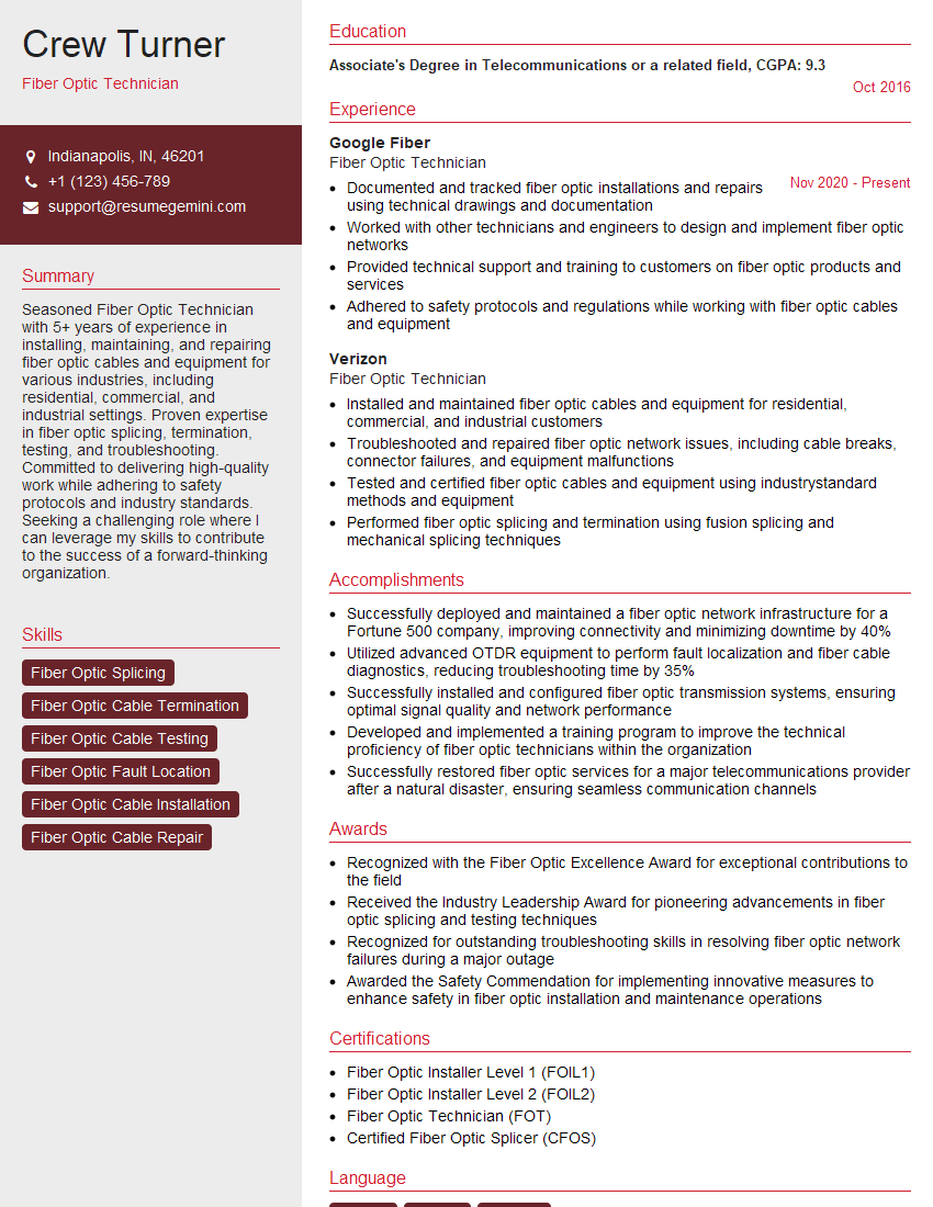
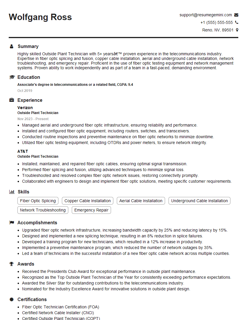
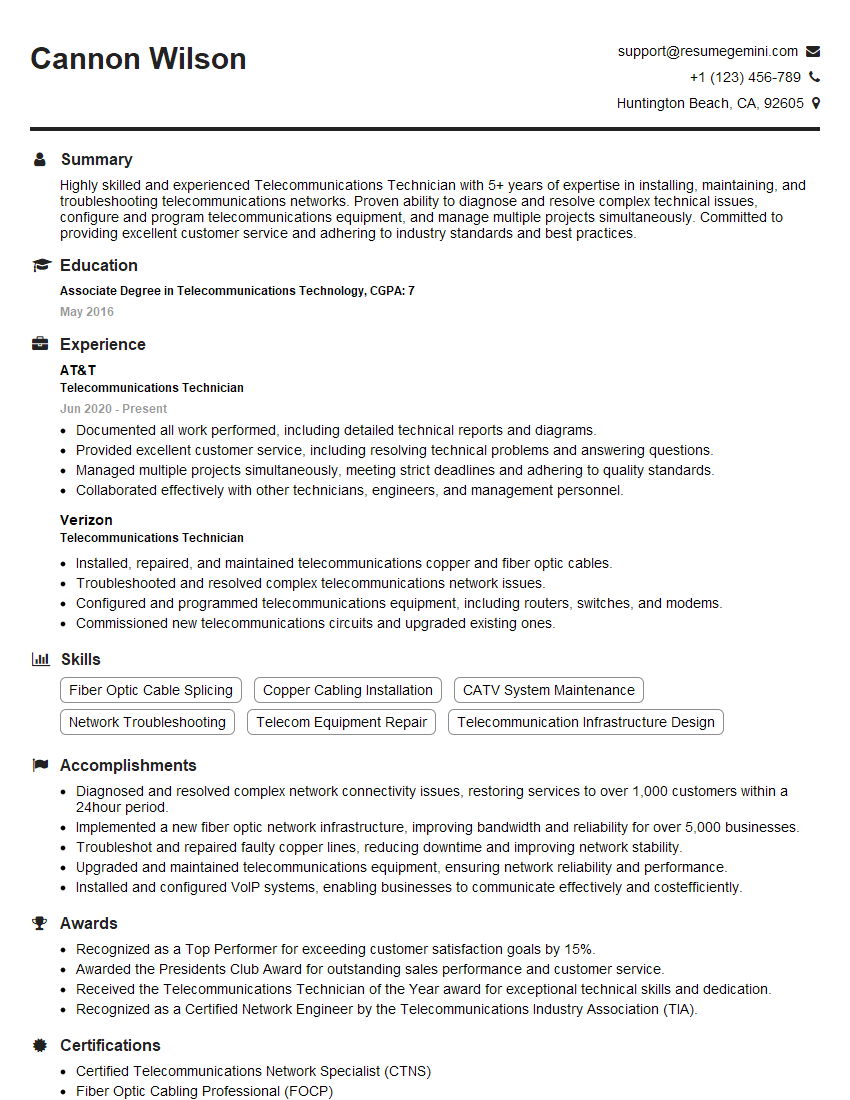
Mastering fiber patching skills opens doors to exciting career opportunities in telecommunications, data centers, and networking. To significantly increase your chances of landing your dream job, creating a compelling and ATS-friendly resume is paramount. ResumeGemini is a trusted resource that can help you build a professional resume that effectively highlights your skills and experience. ResumeGemini provides examples of resumes tailored to Fiber Patching roles, guiding you through the process of showcasing your expertise to potential employers. Invest the time to craft a strong resume; it’s your first impression and a critical element in your job search.
Explore more articles
Users Rating of Our Blogs
Share Your Experience
We value your feedback! Please rate our content and share your thoughts (optional).
What Readers Say About Our Blog
I Redesigned Spongebob Squarepants and his main characters of my artwork.
https://www.deviantart.com/reimaginesponge/art/Redesigned-Spongebob-characters-1223583608
IT gave me an insight and words to use and be able to think of examples
Hi, I’m Jay, we have a few potential clients that are interested in your services, thought you might be a good fit. I’d love to talk about the details, when do you have time to talk?
Best,
Jay
Founder | CEO

