The right preparation can turn an interview into an opportunity to showcase your expertise. This guide to Drafting and Modeling interview questions is your ultimate resource, providing key insights and tips to help you ace your responses and stand out as a top candidate.
Questions Asked in Drafting and Modeling Interview
Q 1. Explain the difference between 2D and 3D modeling.
The fundamental difference between 2D and 3D modeling lies in their representation of space. 2D modeling creates flat, two-dimensional representations, like blueprints or technical drawings. Think of it like a single photograph – it captures a single perspective. 3D modeling, on the other hand, creates a three-dimensional representation that can be viewed from any angle. It’s like having a physical model, allowing you to walk around and inspect it from all sides. This provides a much richer understanding of the object’s form and spatial relationships.
In practice: A 2D floor plan shows the layout of a room, but a 3D model allows you to visualize the room’s volume, ceiling height, and the placement of objects within the space. 2D excels in showing individual elements in precise detail, while 3D is advantageous for visualising and interacting with the overall design and its components together.
Q 2. What CAD software are you proficient in?
I’m proficient in several CAD software packages, including AutoCAD, Revit, and SolidWorks. My experience with AutoCAD spans over eight years, focusing primarily on 2D drafting and detailed design documentation. Revit has been instrumental in my BIM (Building Information Modeling) work, enabling me to create and manage complex building models. SolidWorks is my go-to for 3D modeling and parametric design, particularly for mechanical and product design projects. I’m also familiar with SketchUp for its intuitive interface and its quick modeling capabilities.
My proficiency isn’t just about knowing the software’s functions; it extends to understanding how to leverage its features to optimize workflows and solve complex design challenges efficiently. For example, I’ve utilized AutoCAD’s dynamic blocks to create reusable components, saving time and ensuring consistency across projects. In Revit, I’ve employed families and templates to standardize building components and automate many design tasks.
Q 3. Describe your experience with BIM (Building Information Modeling).
My BIM experience encompasses the entire lifecycle, from conceptual design to construction documentation and facility management. I’ve used Revit extensively on several large-scale projects, creating detailed building models that integrate architectural, structural, and MEP (Mechanical, Electrical, and Plumbing) systems. This collaborative approach ensures consistency and minimizes conflicts between different disciplines.
For example, on a recent hospital project, the Revit model allowed us to detect and resolve clashes between the ductwork and structural elements before construction began, saving significant time and cost. Beyond clash detection, the BIM model served as the central source of truth for all project information, facilitating communication, cost estimation, and scheduling.
I understand the importance of using BIM software to its full potential, beyond merely creating a 3D model. This includes creating schedules, quantity takeoffs, and generating visualizations for presentations and client communication.
Q 4. How do you handle revisions and updates to existing models?
Handling revisions and updates efficiently is crucial. My approach involves version control and a clear change management process. I typically utilize the revision capabilities within the CAD software itself, creating new revisions and maintaining a history of changes. This allows easy tracking of modifications and rollback if needed. Furthermore, I use cloud-based storage solutions to ensure that all team members have access to the latest version and to maintain a secure backup. Before implementing any change, I always communicate with the relevant stakeholders to ensure that the proposed revision aligns with the project goals.
For example, If a client requests a change to a wall’s location in a Revit model, I would create a new revision, document the change, and update the relevant drawings and schedules. This ensures clarity and traceability of the modification.
Q 5. Explain your process for creating detailed technical drawings.
Creating detailed technical drawings is a systematic process that I approach meticulously. It begins with a thorough understanding of the project requirements and the intended use of the drawings. My process generally includes these steps:
- Conceptualization and Planning: Defining the scope, scale, and level of detail required.
- Model Creation (if applicable): Developing a 3D model to serve as a basis for the drawings.
- View Creation and Annotation: Generating appropriate views (plan, section, elevation, detail), adding dimensions, notes, and other annotations.
- Material Selection: Specifying materials and finishes.
- Review and Quality Check: Thoroughly reviewing the drawings for accuracy, completeness, and adherence to standards.
- Revision and Updates: Making necessary changes based on feedback and revisions.
Throughout this process, I maintain consistency in the style and format of my drawings, ensuring clarity and ease of understanding for the intended audience.
Q 6. What are some common drafting standards you follow?
I adhere to various drafting standards depending on the project’s requirements and location. These commonly include:
- ISO (International Organization for Standardization): A globally recognized set of standards for technical drawings.
- ANSI (American National Standards Institute): Widely used in the United States.
- ASME (American Society of Mechanical Engineers): Specific standards for mechanical drawings.
- Local building codes: Regional regulations often dictate specific requirements for architectural and structural drawings.
My experience includes adapting to different standards and ensuring compliance throughout the design process. Understanding and implementing these standards guarantees clarity, accuracy, and seamless communication across different teams and organizations. For instance, correct layering and annotation according to ANSI is critical for quick review by architects or contractors.
Q 7. Describe your experience with different file formats (e.g., DWG, DXF, STEP).
I have extensive experience working with various file formats, including:
- DWG (Drawing): Autodesk’s native format, offering flexibility and compatibility within the AutoCAD ecosystem.
- DXF (Drawing Exchange Format): A neutral format enabling interoperability between different CAD software. This is essential for collaboration and data exchange.
- STEP (Standard for the Exchange of Product model data): A widely used neutral format for 3D models, suitable for exchanging data between different CAD and CAM (Computer-Aided Manufacturing) systems. It’s particularly useful for complex designs with many details. I’ve used this extensively for transferring designs between different software such as SolidWorks and Revit.
- PDF: I use PDFs for sharing final, immutable versions of drawings with clients and for archiving purposes.
Understanding the strengths and limitations of each format helps me choose the most appropriate one for different tasks. For instance, DWG is ideal for project-specific workflows, while DXF or STEP are better suited for transferring data to external parties or other software systems. PDF is perfect for final deliverables.
Q 8. How do you ensure accuracy and precision in your models?
Accuracy and precision in modeling are paramount. Think of it like building a house – a millimeter off here and there might seem insignificant, but cumulatively, it leads to significant issues. I ensure accuracy through a multi-pronged approach:
- Precise Input Data: I meticulously verify all source data, whether it’s survey data, existing drawings, or specifications. Any inaccuracies at this stage will propagate throughout the model.
- Constraint-Based Modeling: I heavily rely on geometric constraints within CAD software. These constraints define relationships between elements (e.g., parallelism, perpendicularity, distances), ensuring the model remains consistent and accurate even after modifications.
- Regular Checks and Validation: Throughout the modeling process, I perform regular checks using built-in tools within the software, such as model diagnostics and interference detection. This helps identify and rectify errors early on.
- Real-World Verification (where possible): When feasible, I compare the model to physical measurements or site surveys to confirm its accuracy. For instance, when modeling a bridge, comparing the model’s dimensions against actual site measurements is crucial.
- Version Control: Using a robust version control system helps track changes, revert to previous versions if errors occur, and maintain a clean and accurate model history.
For example, when modeling a complex assembly, I would first define the key dimensions and relationships using constraints, then progressively build up the model, frequently checking for interferences and ensuring everything aligns perfectly.
Q 9. What methods do you use for quality control in drafting and modeling?
Quality control in drafting and modeling is an ongoing process, not a one-time event. I employ several methods:
- Regular Model Reviews: I conduct thorough reviews of my models at various stages of development, looking for discrepancies, errors, or areas needing improvement. A fresh pair of eyes can often catch mistakes I might have overlooked.
- Automated Checks: CAD software offers built-in tools for automated checks, such as clash detection, dimension checks, and geometric analysis. I utilize these tools extensively to identify potential problems automatically.
- Drawing Standards Compliance: I adhere strictly to relevant drawing standards (e.g., ISO, ANSI) to ensure consistency, clarity, and professional presentation of the drawings.
- Peer Reviews: When working on large projects, peer reviews are invaluable. Having another experienced drafter or modeler review my work helps identify potential flaws and ensures quality.
- Third-Party Verification (when required): For critical projects, I may utilize third-party verification to ensure independent assessment of the model’s accuracy and compliance with standards.
For instance, in a large architectural project, I would use clash detection software to identify interferences between MEP (Mechanical, Electrical, Plumbing) systems and architectural elements before construction begins, saving time and preventing costly rework.
Q 10. How do you manage large and complex models?
Managing large and complex models requires a strategic approach. It’s like managing a large city – you need efficient systems and organization. My strategies include:
- Modular Modeling: I break down large models into smaller, manageable modules. This improves performance, simplifies modifications, and makes collaboration easier. Think of it as building a skyscraper floor by floor, rather than all at once.
- Component Libraries: I utilize and develop component libraries to store frequently used elements, saving time and ensuring consistency across multiple projects. This is like having a library of pre-fabricated building components.
- Effective Naming Conventions: A clear and consistent naming convention for model elements is critical for organization and understanding. It’s like having a well-organized filing system for all your documents.
- Data Management: Using a robust data management system is essential to track revisions, manage files efficiently, and avoid data loss. This is crucial for collaboration within a team.
- Level of Detail (LOD): Employing different levels of detail based on the project requirements helps manage file size and computational demands. You wouldn’t model every individual brick in a building; you’d use simplified representations in early design stages.
For example, in a large-scale infrastructure project, I would model different sections (roadways, bridges, utilities) as separate modules, then integrate them later.
Q 11. Describe your experience with layering and organization in CAD software.
Layering and organization are fundamental in CAD software. Think of it as painting a picture – you wouldn’t paint everything on one canvas. My experience involves:
- Logical Layer Structure: I organize layers logically, using descriptive names (e.g., ‘Structural’, ‘MEP’, ‘Architectural’) to easily identify and manage different elements. This makes it easy to turn layers on or off as needed for specific views.
- Color-Coding: Consistent color-coding helps quickly identify different types of elements. For example, structural elements might be grey, while MEP systems are color-coded by type.
- Layer Properties: I make use of layer properties such as line weight, line style, and transparency to control the visual representation of elements. This ensures clarity in drawings and model visualization.
- Layer Visibility Control: This functionality allows me to selectively hide or show layers, improving clarity and making it easier to focus on specific areas of the model.
- Nested Layers (when appropriate): For complex systems, I may create nested layers to further organize elements within a specific category. This is like having folders within folders on your computer.
For example, in a building model, I’d create separate layers for walls, floors, roofs, doors, windows etc. This makes it easy to modify or select specific components without affecting others.
Q 12. Explain your understanding of orthographic and isometric projections.
Orthographic and isometric projections are fundamental to technical drawing. Orthographic projections show multiple views of an object (front, top, side) to fully describe its shape, like a blueprint. Isometric projections show a single view with all three axes at angles, offering a three-dimensional representation but without true perspective.
- Orthographic Projections: These are essential for precise representation and manufacturing. They provide accurate dimensions and details in each view, allowing for clear understanding of the object’s geometry. The views are usually aligned along the primary axes (X, Y, Z).
- Isometric Projections: These are useful for visual communication, giving a quick 3D impression of the object. They’re often used in presentations or to illustrate overall form, though they may not be suitable for detailed dimensional information.
Imagine designing a chair. Orthographic drawings would show the front, side, and top views with exact dimensions for each part. An isometric drawing would provide a 3D sketch, giving a quick visual representation of the chair’s overall shape.
Q 13. How do you create and interpret sections and details in drawings?
Sections and details are crucial for conveying information about internal structure and specific components. A section cut through an object reveals its internal features; a detail enlarges a small area to show intricate details.
- Creating Sections: Sections are created by virtually cutting through the model along a plane. CAD software provides tools to automatically generate sectional views, showing the object’s internal structure. The section lines and hatching style are important for clarity.
- Creating Details: Details are created by isolating and enlarging a specific area of the model. These are vital for showing complex features or small components with greater precision. Proper annotation is critical.
- Interpreting Sections and Details: Understanding how sections and details are presented is important to correctly interpret the drawing. Section lines, hatching patterns, and annotations guide the viewer to understand the internal geometry and specific components.
For example, in a building design, a section through a wall would show the layering of materials (brick, insulation, drywall), while a detail would show the exact specifications of a window frame and its connections.
Q 14. Describe your experience with creating dimensioned drawings.
Creating dimensioned drawings is crucial for conveying precise information to manufacturers or contractors. It’s like providing a recipe – precise measurements are essential for the final product to be correct.
- Dimensioning Standards: I adhere strictly to relevant dimensioning standards (e.g., ANSI, ISO) to ensure consistency and clarity. These standards define the placement, style, and units of dimensions.
- Dimension Styles: CAD software allows customization of dimension styles (e.g., text size, arrowhead style, units) to maintain consistent presentation.
- Dimension Placement: Careful placement of dimensions is critical for clarity. Dimensions should be clear, unambiguous, and easy to read. Overcrowding should be avoided.
- Tolerance Specification (when necessary): For critical dimensions, tolerances are specified to define the acceptable range of variation.
- Geometric Dimensioning and Tolerancing (GD&T): For complex parts, GD&T symbols are used to precisely define geometric tolerances.
For instance, in a mechanical drawing, I would precisely dimension all critical lengths, diameters, and angles, ensuring that all dimensions are clear, correctly placed, and conform to the relevant standard.
Q 15. How do you handle conflicting design requirements?
Conflicting design requirements are a common challenge in drafting and modeling. My approach is systematic and involves clear communication and prioritization. First, I meticulously document all requirements, identifying any inconsistencies or overlaps. Then, I schedule a meeting with stakeholders – engineers, clients, and other designers – to openly discuss the conflicting points. We use a prioritization matrix, weighing factors like feasibility, cost, and impact on the overall design. This collaborative process often leads to compromises or revised requirements that satisfy most, if not all, stakeholders. For example, if a client wants a highly detailed model but the budget limits the available time, we might compromise on the level of detail in certain less critical areas. Finally, I document the agreed-upon changes, ensuring everyone is on the same page and minimizing future misunderstandings.
Career Expert Tips:
- Ace those interviews! Prepare effectively by reviewing the Top 50 Most Common Interview Questions on ResumeGemini.
- Navigate your job search with confidence! Explore a wide range of Career Tips on ResumeGemini. Learn about common challenges and recommendations to overcome them.
- Craft the perfect resume! Master the Art of Resume Writing with ResumeGemini’s guide. Showcase your unique qualifications and achievements effectively.
- Don’t miss out on holiday savings! Build your dream resume with ResumeGemini’s ATS optimized templates.
Q 16. Explain your experience with creating technical illustrations.
I have extensive experience creating technical illustrations, ranging from simple exploded views to complex assembly drawings and 3D renderings. My expertise includes using software like AutoCAD, SolidWorks, and Adobe Illustrator to produce high-quality, accurate visuals. I understand the importance of clarity and precision in technical illustrations. For instance, in creating an exploded view of a mechanical assembly, I meticulously ensure each component is clearly labeled and positioned to showcase its relationship within the assembly, avoiding ambiguity. In creating 3D renderings, I use lighting and shading techniques to enhance visual understanding and highlight critical features. I’m proficient in producing both static and animated illustrations depending on the project’s needs.
Q 17. How do you collaborate with other team members on design projects?
Collaboration is crucial in design projects. I actively participate in team meetings, utilizing tools like project management software (e.g., Asana, Jira) to track progress, assign tasks, and manage deadlines. Effective communication is key; I leverage various methods such as regular check-ins, design reviews, and shared online platforms to ensure everyone stays informed and aligned. For example, during a recent project involving a complex building design, our team utilized a cloud-based model repository to allow simultaneous access and modifications, fostering real-time collaboration and conflict resolution. Open feedback and a willingness to incorporate diverse perspectives are crucial to my collaborative approach.
Q 18. How do you stay updated on the latest drafting and modeling software and techniques?
Staying current in drafting and modeling is essential. I achieve this through a multi-pronged approach. Firstly, I actively participate in online forums and communities dedicated to CAD software and modeling techniques. Secondly, I subscribe to industry publications and attend webinars or online courses offered by software vendors and professional organizations. This allows me to learn about new features, best practices, and emerging trends. I also regularly complete personal projects to practice and experiment with new tools and techniques. Finally, I seek out opportunities to work on projects that challenge me and push my skills to the next level.
Q 19. Describe a challenging drafting or modeling project you worked on and how you overcame obstacles.
A particularly challenging project involved designing a complex, multi-component injection molding tool. The initial design proved difficult to manufacture due to undercuts and complex parting lines. I overcame this obstacle by using advanced techniques in SolidWorks, such as creating custom parting lines and employing moldflow analysis to simulate the injection molding process. This allowed me to identify and address potential issues early in the design phase, significantly reducing manufacturing costs and improving the overall design. I also collaborated closely with the manufacturing team, incorporating their feedback throughout the design process. The resulting design was successfully manufactured and met all client specifications.
Q 20. What are your preferred methods for troubleshooting drafting and modeling issues?
My troubleshooting approach is systematic. I start by carefully reviewing the model for errors, using the software’s built-in diagnostic tools. If the issue persists, I then analyze the design history to identify the source of the problem. This often involves examining the modeling steps or parameters to pinpoint where the error might have originated. If internal diagnostics fail, I leverage online resources like forums or the software vendor’s support documentation. In some instances, it’s helpful to recreate a simplified version of the problematic section to isolate the issue. Documentation of the problem and its solution is vital for future reference.
Q 21. How do you utilize parametric modeling techniques?
Parametric modeling is a cornerstone of my workflow. I extensively utilize its features to create flexible and adaptable designs. For instance, instead of manually adjusting dimensions, I define parameters that control various aspects of the design, such as lengths, widths, and thicknesses. This allows me to easily modify the model by changing the parameters, automatically updating all dependent elements. This is especially useful when exploring design alternatives or adapting designs based on client feedback. For example, if a client requests a change in the overall length of a component, I can simply adjust the relevant parameter, and the software automatically updates all related dimensions and features, saving significant time and effort.
Q 22. Explain your understanding of tolerance and dimensioning standards.
Tolerance and dimensioning standards are fundamental in drafting and modeling, ensuring that manufactured parts fit together correctly and function as intended. Tolerances define the permissible variation in a dimension, while dimensioning provides the nominal size and its allowed deviation. Think of it like baking a cake: the recipe gives the nominal amounts (dimensions), but a little extra or less flour (tolerance) won’t ruin the cake, whereas too much or too little wouldn’t work.
Different standards exist, like ISO (International Organization for Standardization) and ASME (American Society of Mechanical Engineers) Y14.5, which dictate how tolerances are specified using symbols and annotations on drawings. For example, Ø10 ±0.1 indicates a diameter of 10 units with a tolerance of ±0.1 units. This means the actual diameter can range from 9.9 to 10.1 units. The choice of standard depends on the project’s requirements and industry practices. Geometric Dimensioning and Tolerancing (GD&T) adds another layer, specifying tolerances on form, orientation, location, and runout – crucial for precise assembly and functionality. For instance, specifying perpendicularity tolerance ensures two surfaces are at a right angle within an acceptable range. I have extensive experience working with both ISO and ASME standards, tailoring my approach based on the specific project needs and client requirements.
Q 23. How do you ensure models are compatible with different software applications?
Model compatibility across different software applications is paramount for efficient collaboration and data exchange. The key is to utilize neutral file formats like STEP (Standard for the Exchange of Product model data) or IGES (Initial Graphics Exchange Specification). These formats act as intermediaries, allowing models created in one CAD software (e.g., SolidWorks) to be opened and worked on in another (e.g., Autodesk Inventor) with minimal data loss. However, some minor geometric discrepancies might occasionally occur during translation. Therefore, meticulous file checking is often necessary.
Furthermore, understanding the strengths and limitations of each software is crucial. For instance, some software excels at surface modeling, while others are better suited for solid modeling. Choosing the appropriate software for each stage of the project enhances efficiency. In my experience, I often export models to STEP or IGES formats to facilitate seamless collaboration with clients and colleagues using different software platforms. I also routinely test the compatibility of the models by opening them in multiple programs before finalizing the design, ensuring smooth data exchange throughout the project lifecycle.
Q 24. What is your experience with data extraction from models?
Data extraction from models is crucial for various downstream applications, including manufacturing, analysis, and documentation. My experience includes using various methods to extract data, depending on the desired information and target application.
For example, I frequently extract dimensional data directly from the model to create manufacturing drawings. I also use model analysis tools within the CAD software itself to extract parameters like volume, mass, or center of gravity, useful in design optimization. More complex data extraction tasks might involve scripting or using specialized plugins to export data in a structured format (e.g., CSV or XML) for analysis in external software like spreadsheet programs or finite element analysis (FEA) packages. I’m proficient in using both built-in CAD software tools and external scripting languages to automate data extraction processes, significantly improving efficiency and accuracy. For example, extracting a bill of materials (BOM) directly from a complex assembly model is greatly simplified through automation, leading to significant time savings and fewer errors compared to manual extraction.
Q 25. Describe your experience with rendering and visualization techniques.
Rendering and visualization are critical for communicating design intent effectively and showcasing the model’s aesthetics and functionality. My experience encompasses various techniques, from simple wireframe renders to photorealistic visualizations using advanced rendering software and techniques.
I’m proficient in using rendering tools within CAD software and dedicated rendering packages like Keyshot or V-Ray. I understand the importance of lighting, materials, and camera angles to create compelling visuals. For example, creating realistic product renderings that accurately depict materials and lighting conditions is crucial for marketing purposes. I also have experience using animation techniques to demonstrate product functionality or manufacturing processes, creating walkthroughs, and fly-throughs that significantly improve understanding. The choice of rendering technique depends greatly on the project requirements. For initial design reviews, simpler renderings might suffice, but for marketing materials or client presentations, high-quality photorealistic renders are often required.
Q 26. How do you manage and organize your project files effectively?
Effective file management is crucial to maintain project sanity, especially on large or complex projects. I use a structured folder system to organize my files, typically mirroring the project’s breakdown. This usually means having a dedicated folder for each project, further subdivided into folders for drawings, models, renderings, and documentation.
I consistently use descriptive file naming conventions, incorporating project identifiers, revision numbers, and date stamps for easy identification and retrieval. This reduces the time spent searching for specific files. Furthermore, I regularly back up my work to a cloud-based storage system and maintain local backups as well. Version control systems, like those integrated within CAD software or external solutions, help manage different revisions and track changes over time. Finally, I maintain a comprehensive project log, documenting file changes, decisions, and important interactions for seamless collaboration and reference. This method provides a clear audit trail for any project modifications, significantly simplifying troubleshooting and collaborative workflows.
Q 27. What are your strengths and weaknesses as a drafter and modeler?
My strengths lie in my meticulous attention to detail, problem-solving skills, and proficiency in various CAD software packages. I thrive in collaborative environments and am adept at adapting to new technologies and challenges. I’m also capable of quickly grasping project requirements and translating them into efficient workflows. A recent project involved a complex assembly with tight tolerance requirements. My attention to detail and experience with GD&T ensured that the final model met all specifications, preventing costly manufacturing issues.
One area I’m continuously working on is expanding my knowledge of advanced scripting and automation techniques within the CAD software to further streamline my workflows and reduce reliance on manual processes. This is an area of active learning, where I seek opportunities to improve my skills and stay updated on the latest technological advancements. For instance, leveraging scripting to automatically generate reports and extract data is a significant area of focus for improving overall efficiency.
Key Topics to Learn for Drafting and Modeling Interview
- Fundamentals of CAD Software: Mastering the software you’ll be using (AutoCAD, Revit, SolidWorks, etc.) is paramount. Focus on proficiency in 2D and 3D modeling, including drawing creation, modification, and annotation.
- Geometric Dimensioning and Tolerancing (GD&T): Understand how GD&T symbols and standards define tolerances and ensure part functionality. Practice interpreting and applying GD&T specifications in your models.
- Blueprint Reading and Interpretation: Demonstrate your ability to accurately read and understand technical drawings, including orthographic projections, sections, and details. Be prepared to explain different drawing types and their purposes.
- Design for Manufacturing (DFM): Show your understanding of how design choices impact manufacturing processes. This includes material selection, assembly considerations, and cost implications.
- 3D Modeling Techniques: Practice various 3D modeling techniques like solid modeling, surface modeling, and wireframe modeling. Be ready to discuss the advantages and disadvantages of each technique and their applications.
- Drafting Standards and Conventions: Familiarize yourself with industry-standard drafting practices and conventions to ensure your drawings are clear, consistent, and easily understood by others.
- Problem-Solving and Collaboration: Be ready to discuss your approach to problem-solving in a design context, and highlight your teamwork and communication skills in a collaborative design environment.
- Material Properties and Selection: Understand the properties of different materials and how to select appropriate materials based on the design requirements and application.
Next Steps
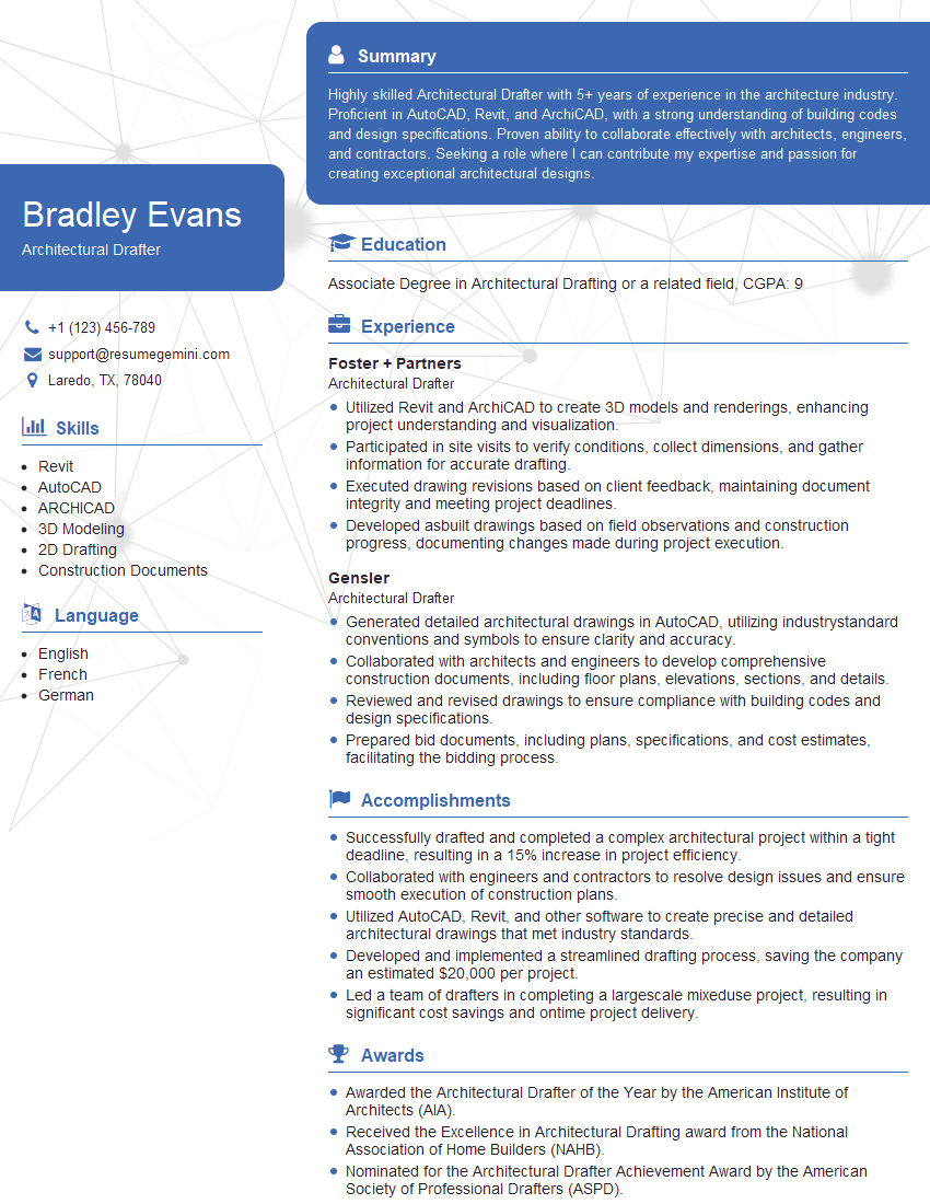
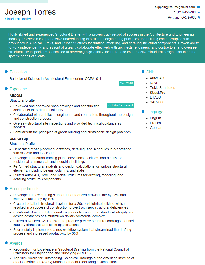
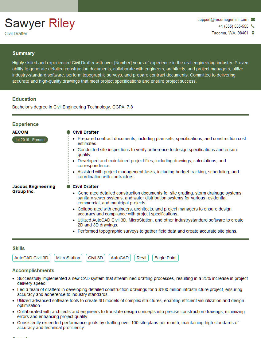
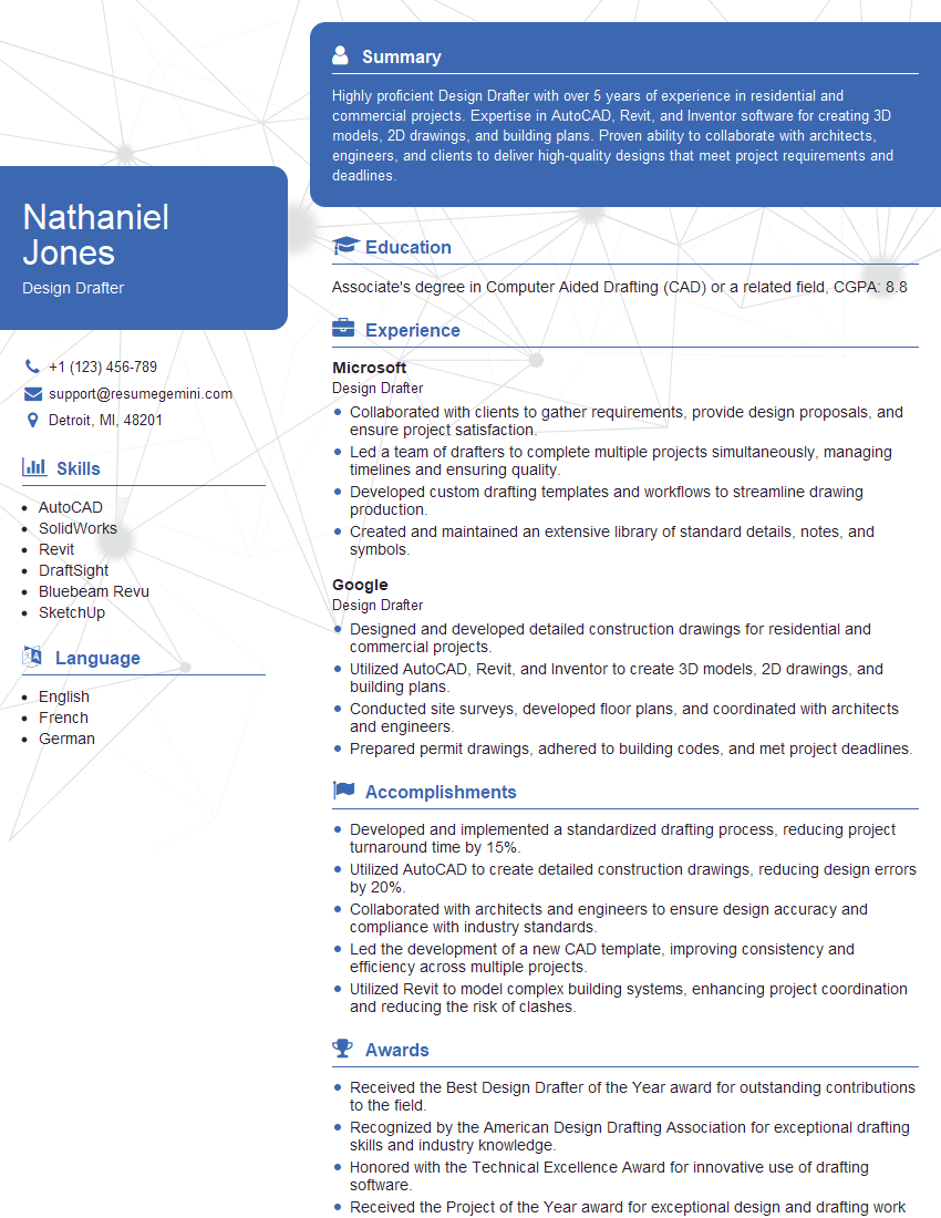
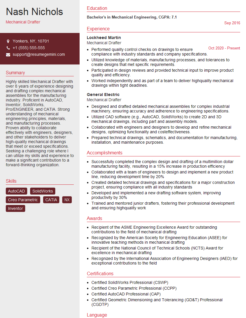
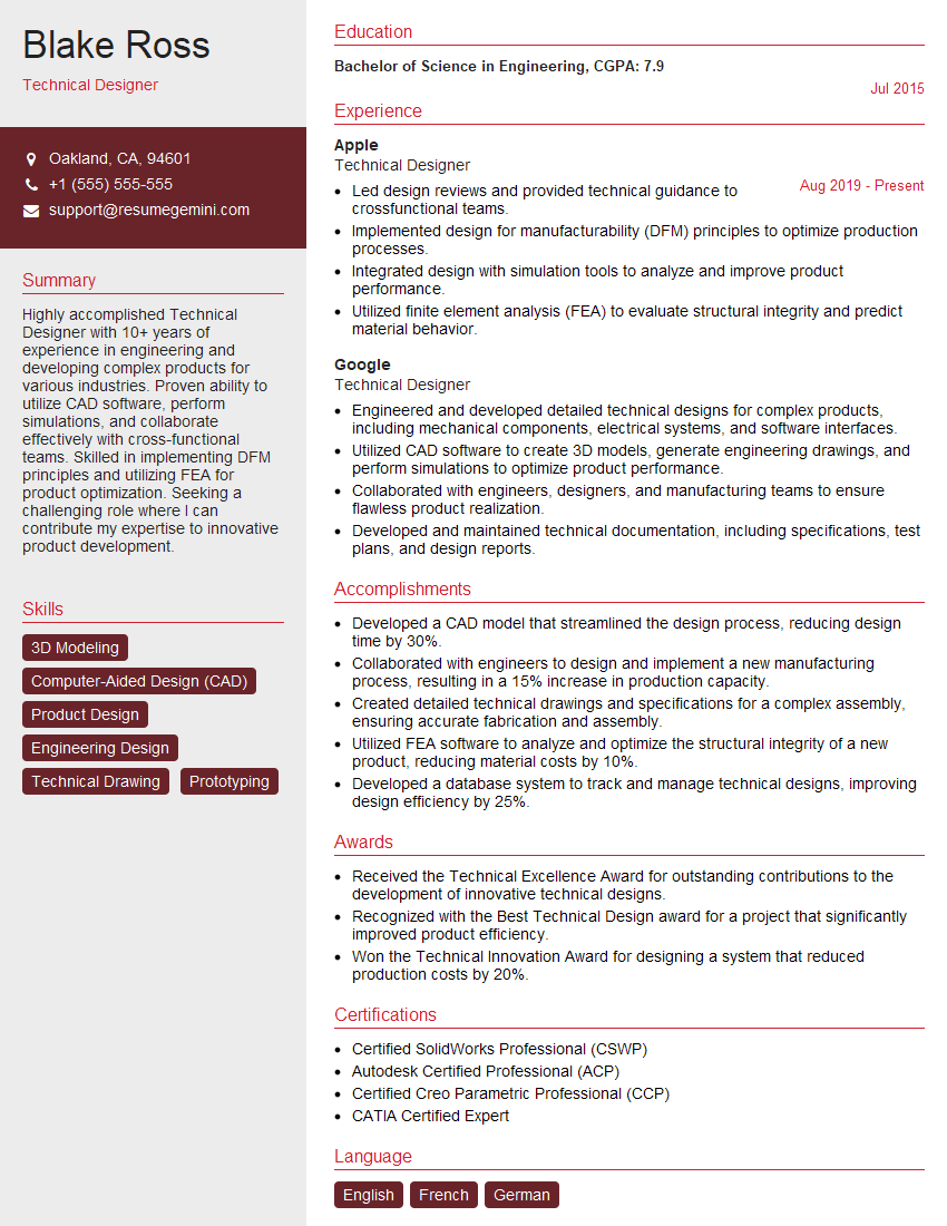
Mastering Drafting and Modeling skills opens doors to exciting and rewarding careers in engineering, architecture, and manufacturing. To maximize your job prospects, crafting a strong, ATS-friendly resume is crucial. This ensures your qualifications are effectively highlighted to potential employers. ResumeGemini is a trusted resource to help you build a professional and impactful resume tailored to your specific skills. Examples of resumes optimized for Drafting and Modeling positions are available to help guide your creation process. Take this opportunity to showcase your expertise and land your dream job!
Explore more articles
Users Rating of Our Blogs
Share Your Experience
We value your feedback! Please rate our content and share your thoughts (optional).
What Readers Say About Our Blog
Hi, I’m Jay, we have a few potential clients that are interested in your services, thought you might be a good fit. I’d love to talk about the details, when do you have time to talk?
Best,
Jay
Founder | CEO
