The right preparation can turn an interview into an opportunity to showcase your expertise. This guide to Experienced in using CAD software for survey drafting and mapping interview questions is your ultimate resource, providing key insights and tips to help you ace your responses and stand out as a top candidate.
Questions Asked in Experienced in using CAD software for survey drafting and mapping Interview
Q 1. What CAD software are you proficient in?
I’m proficient in several CAD software packages, but my primary expertise lies in AutoCAD Civil 3D and MicroStation. AutoCAD Civil 3D is my go-to for its powerful tools specifically designed for surveying and civil engineering tasks, such as surface modeling, corridor design, and quantity take-offs. MicroStation offers a robust platform for large-scale projects and complex data integration. I’ve also had experience with ArcGIS for integrating survey data with GIS information. My proficiency extends beyond basic drafting; I’m comfortable using advanced features like dynamic blocks, custom linetypes, and data linking for efficient workflow management.
Q 2. Explain your experience with coordinate systems (e.g., UTM, State Plane).
Coordinate systems are fundamental in surveying. Understanding UTM (Universal Transverse Mercator) and State Plane coordinate systems is crucial for accurate mapping. UTM divides the Earth into 60 zones, each using a transverse Mercator projection, minimizing distortion within each zone. State Plane coordinates are tailored to individual states, offering higher accuracy within their boundaries. I have extensive experience transforming coordinates between different datums (e.g., NAD83 to NAD27) and projections. For example, I once worked on a project involving data from multiple surveys, each using a different coordinate system. My ability to accurately transform these coordinates into a unified system was critical in ensuring the project’s accuracy and consistency. I’m familiar with using coordinate transformation tools within CAD software and also leverage external software like geographic coordinate transformation applications to accomplish this.
Q 3. Describe your workflow for creating a survey plan from field data.
My workflow for creating a survey plan from field data is methodical and follows a structured approach. First, I import the field data, typically in a format like DXF or CSV, into my chosen CAD software. Then I perform a thorough data check for any outliers or inconsistencies. Next, I establish a coordinate system and create the base map. This might involve importing existing maps or creating one from scratch using control points. After that, I digitize the survey data, creating points, lines, and polygons representing the features surveyed. Finally, I generate the plan, adding labels, annotations, and any necessary calculations (e.g., area calculations). For instance, if processing data from a Total Station, I’ll use the software’s import capabilities to directly incorporate the data, reducing the possibility of manual data entry errors. This entire process is meticulously documented to maintain transparency and traceability.
Q 4. How do you handle errors or discrepancies in survey data?
Handling errors or discrepancies in survey data requires a careful and systematic approach. I begin by identifying the source of the error. This may involve reviewing the field notes, checking the instrument calibration logs, or analyzing the data for outliers. Once identified, I investigate to determine the likely cause of the discrepancy. For example, if I find a significant discrepancy between GPS data and ground measurements, I would check for potential sources of error like multipath interference or inaccurate GPS base station data. Then, depending on the severity and nature of the error, I might correct it, flag it for further investigation, or exclude it from the analysis. Documentation of these actions is paramount. In short, my approach is data-driven, prioritizing accuracy and transparency. Every decision related to data handling is thoroughly recorded.
Q 5. What are your methods for quality control in CAD drafting for surveys?
Quality control is ingrained in my CAD drafting process. It starts with verifying the accuracy of the input data. I regularly use tools within the software to check for coordinate inconsistencies, overlapping lines, or gaps in the data. Next, I perform geometric checks – ensuring that angles and distances adhere to the original survey measurements. I then apply layer management and labeling standards for clarity. This includes using standardized linetypes, fonts, and annotation styles. Regular backups are also a key component of my quality control to prevent data loss. Lastly, I always conduct a final visual review of the completed drawing to identify any potential issues before finalizing the plan. This multi-faceted approach ensures the final product is accurate, consistent, and easy to understand. Think of it as a systematic process – checking and rechecking at each stage.
Q 6. Explain your experience with creating contour lines from survey data.
Creating contour lines is a common task in survey drafting. I typically use the surface modeling capabilities within CAD software like AutoCAD Civil 3D or MicroStation. These programs allow you to create a 3D surface model from the elevation data collected during the survey. Once the surface is created, I use the software’s contouring tools to generate contour lines at specified intervals. The accuracy of the contour lines depends heavily on the density and quality of the original survey data. I’ve found that visualizing the surface model in 3D provides valuable insight into potential errors or anomalies in the data before generating the final contours. For instance, I once identified a significant elevation discrepancy during surface model creation, allowing me to correct a field data error before creating the final contour map.
Q 7. How do you ensure accuracy and precision in your CAD drawings?
Ensuring accuracy and precision in CAD drawings is paramount. This begins with proper data input and verification as previously discussed. Using precise coordinate systems and working to a defined level of precision (e.g., specifying drawing units to millimeters) are critical. I frequently use software tools to check for geometric inconsistencies and perform coordinate geometry calculations. For instance, I regularly check the closure of traverses and the accuracy of area calculations. Using dynamic blocks, where applicable, enforces consistency and reduces errors by automatically updating linked parameters. Finally, regular quality checks throughout the drafting process, as described in my answer to question 5, are crucial for maintaining high accuracy and precision. A final plot check against the physical site (if possible) adds an extra layer of assurance.
Q 8. Describe your experience with creating and editing digital terrain models (DTMs).
Creating and editing Digital Terrain Models (DTMs) is a core part of my surveying workflow. A DTM is a digital representation of the Earth’s surface, showing elevation data. I’ve extensively used software like AutoCAD Civil 3D and ArcGIS Pro to build these models. My process typically involves several steps:
- Data Acquisition: This begins with collecting elevation data, often from LiDAR surveys, total station measurements, or contour lines from existing maps. I meticulously check the data for accuracy and completeness, identifying and addressing any outliers or gaps.
- Data Import and Processing: I import the data into the chosen CAD software. This might involve converting point clouds (from LiDAR) into a usable format or digitizing contour lines. I then use the software’s tools to clean and process the data, removing noise and interpolating missing values to create a smooth surface.
- DTM Creation: The software uses sophisticated algorithms (like TIN – Triangulated Irregular Network or grid interpolation) to generate the DTM. I carefully review the resulting model, checking for anomalies and adjusting parameters as needed to achieve the desired level of detail and accuracy.
- DTM Editing and Analysis: Once created, I can edit the DTM, for example, to correct errors or incorporate new data. I also use the model for analysis – calculating slopes, aspects, and volumes – crucial information for various engineering and planning projects.
For example, on a recent highway project, I used LiDAR data to create a highly accurate DTM, which was essential for designing safe and efficient road alignments and calculating earthwork volumes.
Q 9. What is your experience with different map projections?
Map projections are crucial for accurately representing the three-dimensional Earth on a two-dimensional map. Different projections distort distances, areas, and shapes differently, depending on their purpose and the region being mapped. My experience encompasses several common projections:
- UTM (Universal Transverse Mercator): Widely used for large-scale mapping, it minimizes distortion within its zones. I frequently utilize UTM for surveying projects that cover relatively small areas.
- State Plane Coordinate Systems: These are tailored to individual states or regions, minimizing distortion within their boundaries. I select the appropriate State Plane coordinate system depending on the project location.
- Geographic Coordinate System (GCS): Uses latitude and longitude, which is often the starting point for project setups. I use GCS to define the global location and then often transform to a projected coordinate system for local surveying work.
- Lambert Conformal Conic: Suitable for areas with predominantly north-south orientations, I’ve used this for projects involving linear features like pipelines or railways.
Choosing the right projection is critical. For instance, using a UTM projection for a large country would lead to unacceptable distortions, while using a State Plane projection for a small local area might be unnecessarily complex. I always carefully consider the project’s scope and required accuracy to select the most appropriate projection.
Q 10. How familiar are you with importing and exporting data in various formats (e.g., DXF, DWG, SHP)?
Data interoperability is paramount in my work. I’m proficient in importing and exporting data in a wide range of formats, including DXF, DWG, SHP, LandXML, and many others. Understanding the nuances of each format is crucial to ensure data integrity and avoid errors.
- DXF (Drawing Exchange Format): A widely accepted vector format, allowing for seamless data exchange between different CAD software packages. I regularly use DXF for sharing survey data with engineers and other stakeholders.
- DWG (Drawing): AutoCAD’s native format. I heavily rely on this for my own projects within the AutoCAD environment.
- SHP (Shapefile): A popular geospatial vector format used for GIS applications. I frequently import SHP files containing boundary information, parcel data, or other geographical features into my CAD drawings to create a comprehensive plan.
For example, I recently received survey data in LandXML format from a client, imported it into Civil 3D, and then exported the processed data as a DXF file for the structural engineers working on the project. Careful attention to coordinate systems and units during import and export is crucial to prevent discrepancies.
Q 11. Describe your process for creating construction drawings from survey data.
Creating construction drawings from survey data is a multi-stage process. It starts with organizing and processing the raw survey data (points, lines, and levels) into a usable format in my chosen CAD software.
- Data Import and Cleaning: I import the data, meticulously checking for errors or inconsistencies. This often involves cleaning up raw data points, eliminating outliers, and ensuring proper coordinate systems.
- Feature Creation: Based on the survey data, I create the key features of the construction drawing. This could include building footprints, road alignments, utility lines, and topography contours.
- Plan Development: I use CAD tools to develop the plan, including site grading, drainage systems, and other essential elements. This phase often involves using DTMs to develop accurate earthwork calculations.
- Annotation and Detailing: I add annotations, dimensions, labels, and other details to ensure the drawing is clear, accurate, and meets project specifications. This often involves applying specific company or project standards.
- Quality Control: Finally, I carefully review and check the drawing for accuracy and completeness before release. This may involve a peer review process to ensure compliance with standards.
For a recent residential development project, I created construction drawings including site grading plans, utility plans, and building foundation plans, all based on my survey data. The accuracy of these drawings was crucial for ensuring the successful completion of the project.
Q 12. How do you manage large datasets in CAD software?
Managing large datasets in CAD software requires efficient strategies to avoid performance issues and maintain data integrity. My approach involves several key techniques:
- Data Optimization: Before importing, I often preprocess the data to remove unnecessary points or features. This significantly reduces file size and improves performance.
- Data Linking: Instead of embedding large datasets directly into the drawing, I often link to external data files. This keeps the main drawing file smaller and faster while still accessing all necessary information.
- Layer Management: Using layers effectively is crucial. I organize data into logical layers, turning off layers I don’t need during specific tasks to improve performance. This also keeps the drawing organized and easier to navigate.
- Data Referencing: Utilizing external references to other drawings or datasets is particularly useful for large projects. It allows for efficient management of large volumes of information.
- Hardware and Software Optimization: Ensuring sufficient RAM, a fast processor, and using a CAD software version optimized for large datasets are also critical.
For example, on a large infrastructure project with several gigabytes of survey data, I employed a combination of data linking, efficient layer management, and external references to manage the dataset effectively within the software without encountering performance issues.
Q 13. Explain your experience with using CAD software for volume calculations.
CAD software provides powerful tools for accurate volume calculations, essential for tasks like earthwork estimations, reservoir capacity assessments, or material quantity determination. My experience includes using various methods:
- DTM-based Volume Calculations: This is the most common approach for calculating earthwork volumes. I use the DTM to define the ground surface and then compare it to a design surface (e.g., proposed road grade) to calculate cut and fill volumes. Software automatically calculates these volumes.
- Cross-Section Method: For linear features like roads or canals, I can use the cross-section method. This involves creating cross-sections at regular intervals along the feature and using the software to calculate the volume between these sections.
- Mass Haul Diagrams: These diagrams visually represent the balance between cut and fill volumes along a linear alignment, helping in optimizing earthwork operations. The CAD software can generate these diagrams automatically based on my DTM and design data.
In a recent dam construction project, I used DTM-based volume calculations to accurately estimate the amount of earthwork required for dam construction and reservoir excavation, allowing for precise material procurement and cost estimation.
Q 14. How do you incorporate GIS data into your survey drawings?
Integrating GIS data into survey drawings enhances their context and provides a more comprehensive understanding of the project area. I typically use several methods to achieve this:
- Direct Import: I directly import GIS data (Shapefiles, GeoTIFFs, etc.) into my CAD software. The software handles the coordinate system transformation, ensuring alignment with my survey data.
- Data Linking: I can link to external GIS databases or files, allowing for dynamic updates as the GIS data changes. This avoids redundant data storage within the CAD drawing.
- Coordinate System Transformation: I meticulously ensure both GIS and survey data share the same coordinate system to prevent misalignment. I often use the software’s tools to perform coordinate transformations between different systems.
- Georeferencing: If the GIS data isn’t already georeferenced, I can do this within the CAD environment, linking it to a known coordinate system using control points.
For example, on a land development project, I imported GIS data showing parcel boundaries, zoning information, and existing utilities. This overlay on my survey data allowed for a complete understanding of the site’s characteristics and constraints, leading to better planning and design decisions.
Q 15. What are your experience with creating and maintaining survey databases?
Creating and maintaining survey databases is crucial for efficient project management and data integrity. My experience involves using various database management systems (DBMS), often integrated with CAD software. This includes designing the database schema – defining tables, fields, and relationships – to accommodate all relevant survey data, such as point coordinates, descriptions, measurements, and associated metadata. I’m proficient in importing data from various sources, ensuring data consistency through validation and error checking, and regularly backing up the database to prevent data loss. For instance, on a recent large-scale land development project, I designed a database that linked survey points to their corresponding design elements, allowing for seamless updates and accurate reporting throughout the project lifecycle. This significantly reduced errors and saved considerable time compared to relying solely on manual data entry and cross-referencing.
My workflow includes establishing clear data entry protocols, implementing quality control checks, and regularly auditing the database for accuracy and completeness. Data visualization tools within the DBMS are also used to identify outliers or potential errors, allowing for prompt correction.
Career Expert Tips:
- Ace those interviews! Prepare effectively by reviewing the Top 50 Most Common Interview Questions on ResumeGemini.
- Navigate your job search with confidence! Explore a wide range of Career Tips on ResumeGemini. Learn about common challenges and recommendations to overcome them.
- Craft the perfect resume! Master the Art of Resume Writing with ResumeGemini’s guide. Showcase your unique qualifications and achievements effectively.
- Don’t miss out on holiday savings! Build your dream resume with ResumeGemini’s ATS optimized templates.
Q 16. What is your proficiency level with creating cross-sections and profiles?
I’m highly proficient in creating cross-sections and profiles using CAD software. This involves extracting data from survey data sets, terrain models, and alignments to generate visual representations of the land’s profile along a specific line. This is essential for tasks such as road design, utility planning, and earthworks calculations. I use a variety of techniques, including automatic generation from digital terrain models (DTMs) and manual adjustments for more precise representation of features like existing structures or underground utilities. For example, when designing a new highway, accurate cross-sections are vital for determining cut and fill volumes and designing appropriate drainage structures.
My proficiency extends to customizing the appearance of these sections, adding annotations and labels for clarity and compliance with industry standards. I also understand the importance of vertical and horizontal scaling, and how changes in these can impact the accuracy and interpretability of the cross-sections.
Q 17. Describe your experience working with different types of survey equipment data.
My experience encompasses working with diverse survey equipment data, including data from Total Stations, GPS receivers, and laser scanners. I understand the different data formats generated by these instruments (e.g., .dxf, .txt, .las) and the specific processes required for importing and processing them within CAD software. For instance, GPS data often requires post-processing to account for atmospheric and satellite errors, and I’m skilled in using appropriate software for this. Data from total stations needs to be checked for consistency and accuracy, often involving coordinate transformation and error analysis.
I’m familiar with various coordinate systems (e.g., UTM, State Plane) and data projections and can convert between different systems as required for specific projects. I also possess the knowledge to identify and address potential inconsistencies or errors in the data, ensuring the resulting CAD drawings are reliable and accurate. A recent project involved integrating data from a LiDAR scan, a total station survey, and existing GIS data to produce a highly accurate 3D model of a complex site.
Q 18. How do you handle conflicting data from different survey sources?
Conflicting data from different survey sources is a common challenge in surveying. My approach involves a systematic investigation, using a combination of data analysis techniques and professional judgment. The first step is to identify the discrepancies and understand the potential causes. This may involve comparing the coordinate systems, checking for measurement errors, or considering the precision and accuracy of the different data sets.
I might use statistical analysis to identify outliers or inconsistencies, and then systematically investigate the source of the error. It could be as simple as a typo in the data entry, or it may require a more in-depth investigation, possibly even a field check to verify the accuracy of the original measurements. If the discrepancies cannot be readily resolved, I’d prioritize the data source with the higher accuracy and precision, documenting the conflict and my resolution process meticulously. Transparency and clear documentation are crucial in these situations.
Q 19. What are your methods for creating and maintaining layer management in CAD?
Effective layer management is essential for organizing and managing complex CAD drawings. My approach involves creating a logical and consistent layer structure based on the project’s requirements. I typically use a hierarchical system, with broader categories at the top and increasingly specific sub-layers below. For example, the top layer might be ‘Site Features’, with sub-layers such as ‘Existing Buildings’, ‘Proposed Buildings’, ‘Utilities’, etc. Each layer has a clearly defined purpose and contains only relevant elements. This approach significantly improves workflow and facilitates efficient modifications, searches, and the management of large and complex projects.
I also utilize layer properties effectively, including color, line weight, linetype, and transparency, to improve visual clarity and differentiate elements on the drawing. Consistent naming conventions and the use of layer states to selectively show or hide layers as needed contribute to a well-organized and manageable drawing environment. Using layer filters and selecting sets can further enhance efficiency.
Q 20. Explain your approach to troubleshooting CAD software issues.
Troubleshooting CAD software issues requires a methodical approach. I begin by identifying the specific error message or symptom, replicating the issue to understand the conditions under which it occurs. My next step involves checking for obvious solutions: checking data integrity, file corruption, software updates, hardware constraints, and reinstalling the software as a last resort.
I’ll also consult the software’s help documentation, online forums, or contact the software vendor’s support team if necessary. For instance, if a drawing is slow to load, I might first check for corrupted blocks or excessive number of layers. If a specific command isn’t working, I’ll verify the system requirements, software updates and compatibility, and check for conflicts with other programs. A systematic approach, paired with knowledge of CAD settings and functionality, usually leads to a rapid resolution.
Q 21. How do you ensure the compatibility of your drawings with different software versions?
Ensuring drawing compatibility across different software versions requires careful consideration of file formats and data structure. I generally favor industry-standard file formats like .dwg (AutoCAD) which are often backward compatible but should be tested with each software version to be certain. However, even with standardized formats, minor discrepancies can occur due to changes in software functionalities.
To mitigate compatibility issues, I meticulously document the software version used to create the drawing. I also avoid using features or settings that are unique to a specific software version and which may not be supported in older versions. Regularly saving the drawing in both the native format and a commonly used format like .dwg can further help prevent this. Saving a version as a PDF can also be useful for sharing and archiving. Before sending drawings to clients or collaborators, I always test the compatibility with their systems to avoid potential problems.
Q 22. Describe your experience with using CAD software for legal boundary descriptions.
My experience with CAD software for legal boundary descriptions is extensive. I’ve used AutoCAD, Civil 3D, and MicroStation to create precise and legally compliant boundary plats. This involves meticulously digitizing field data, ensuring all metes and bounds (distances and directions) are accurately represented. I’m proficient in creating callouts for monumentation, easements, and other critical features. For example, I once worked on a complex property line dispute where precise CAD drafting helped clarify ambiguities in the original deed description, leading to a successful resolution. The key is maintaining a high level of accuracy and adhering to all relevant legal standards and jurisdictional requirements for boundary representation. This includes using appropriate line weights and symbology to distinguish various property lines and features.
Q 23. How familiar are you with various types of survey monuments and markers?
My familiarity with survey monuments and markers is comprehensive. I can identify and differentiate various types, including iron pins, rebar, concrete monuments, and natural markers like trees or rocks. I understand the importance of each type in establishing a property’s boundary. For instance, iron pins are commonly used for their durability, but their precise location can be challenging to determine if disturbed. Concrete monuments, on the other hand, offer greater stability and visibility. Understanding the different types of markers is crucial because their reliability and precision dictate the accuracy of the survey. I’m also well-versed in the legal implications and surveying best practices related to monumentation, including proper recording and handling procedures.
Q 24. Describe your experience with creating and annotating survey plans for different purposes.
Creating and annotating survey plans is a core part of my work. I have experience preparing plans for various purposes, including boundary surveys, topographic surveys, construction staking, and ALTA/ACSM land title surveys. My annotations are clear, concise, and follow industry standards. I ensure that all necessary information – such as bearings, distances, coordinates, and elevations – is accurately depicted and labeled. For example, when creating a construction staking plan, I carefully annotate the locations of building corners, utility lines, and other critical infrastructure. For ALTA surveys, I meticulously label easements and encroachments for use in title insurance. The ultimate goal is to create a plan that’s not just visually appealing but also readily understandable and useful for its intended audience.
Q 25. What is your understanding of scale and precision in surveying and mapping?
Scale and precision are fundamental concepts in surveying and mapping. Scale refers to the ratio between the distance on a map and the corresponding distance on the ground. Precision refers to the degree of accuracy in measurements. A large-scale map (e.g., 1:500) shows greater detail over a smaller area, while a small-scale map (e.g., 1:100,000) covers a larger area with less detail. The level of precision needed depends on the project’s purpose. A construction project might require centimeter-level precision, while a regional planning map may only need meter-level accuracy. I understand how to select appropriate scales and coordinate systems to balance detail and coverage, while always maintaining the required level of precision for the specific project. Incorrect scale or insufficient precision can lead to significant errors in design and construction.
Q 26. How do you adapt to changes in project requirements and deadlines?
Adaptability is key in this field. I’m accustomed to handling changes in project requirements and deadlines. My approach involves maintaining open communication with clients and project managers, promptly addressing any new information or constraints. I prioritize task management and utilize project management software to keep track of progress and anticipate potential delays. For example, I once had to incorporate last-minute changes in a site plan due to newly discovered underground utilities. By proactively communicating the impact and working closely with the client and the utility company, I was able to successfully adjust the project schedule and deliverables without compromising quality.
Q 27. Explain your experience in preparing survey reports and deliverables.
I have significant experience preparing comprehensive survey reports and deliverables. This includes compiling field data, creating accurate maps, writing clear and concise narrative descriptions, and preparing legal descriptions. My reports clearly present findings, analysis, and conclusions, tailored to the specific needs of the client. I also ensure all deliverables meet the standards set by professional organizations, such as the American Congress on Surveying and Mapping (ACSM). For example, a typical boundary survey report would include a detailed map of the property lines, a metes and bounds description of the boundary, and a table of coordinates for all boundary corners. Accuracy, clarity, and completeness are always paramount.
Q 28. Describe your experience with collaborating with other professionals on surveying projects.
Collaboration is essential in surveying projects. I have a strong track record of working effectively with engineers, architects, lawyers, and other professionals. I effectively communicate technical information, actively listen to others’ perspectives, and contribute to a collaborative environment. For instance, I regularly work with engineers to integrate survey data into their designs. Effective communication and a shared understanding of the project goals are crucial for a successful outcome. This includes regular meetings, clear documentation, and the use of shared online platforms for efficient data exchange and communication.
Key Topics to Learn for Experienced in using CAD Software for Survey Drafting and Mapping Interview
- CAD Software Proficiency: Deep understanding of at least one major CAD software (AutoCAD, Civil 3D, MicroStation, etc.), including its interface, tools, and functionalities relevant to surveying and mapping.
- Survey Data Processing: Knowledge of importing and processing survey data (e.g., from total stations, GPS receivers), including data cleaning, error correction, and coordinate transformations.
- Drafting Techniques: Proficiency in creating accurate and detailed survey drawings, including site plans, topographic maps, cross-sections, and profiles, adhering to industry standards and best practices.
- Mapping Principles: Understanding of map projections, coordinate systems, and scale representation. Ability to create maps suitable for various purposes (e.g., construction, land development).
- Annotation and Labeling: Skill in effectively annotating drawings with relevant information (dimensions, elevations, notes, etc.) to ensure clarity and completeness.
- Data Management: Knowledge of efficient data management techniques for large survey datasets, including organization, backup, and retrieval.
- Problem-Solving and Troubleshooting: Ability to identify and resolve issues related to data inaccuracies, software malfunctions, and drafting inconsistencies.
- Industry Standards and Regulations: Familiarity with relevant surveying and mapping standards and regulations.
- Practical Applications: Describe real-world projects where you’ve applied your CAD skills for survey drafting and mapping, highlighting your contributions and problem-solving approaches.
Next Steps
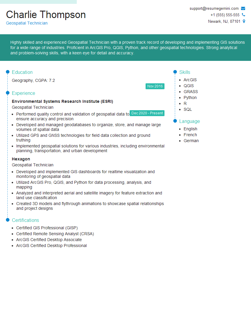
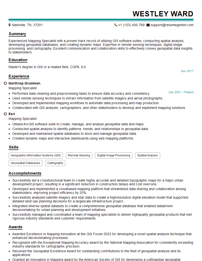
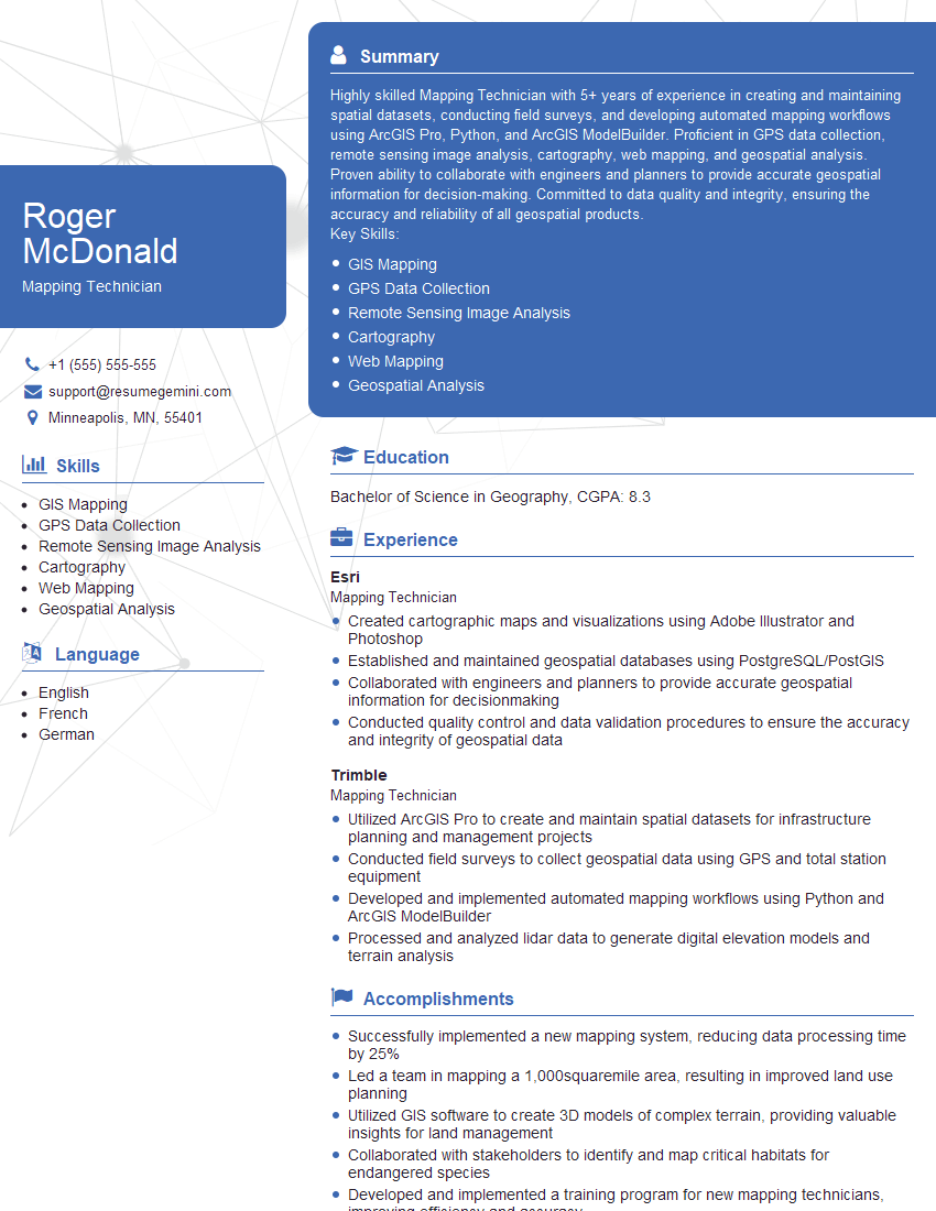
Mastering CAD software for survey drafting and mapping significantly enhances your career prospects in the geospatial industry, opening doors to diverse and challenging roles. An ATS-friendly resume is crucial for getting your application noticed. To make your resume stand out, leverage ResumeGemini to craft a professional and impactful document that showcases your skills effectively. ResumeGemini provides examples of resumes tailored to “Experienced in using CAD software for survey drafting and mapping,” helping you present your experience in the best possible light.
Explore more articles
Users Rating of Our Blogs
Share Your Experience
We value your feedback! Please rate our content and share your thoughts (optional).
What Readers Say About Our Blog
Hi, I’m Jay, we have a few potential clients that are interested in your services, thought you might be a good fit. I’d love to talk about the details, when do you have time to talk?
Best,
Jay
Founder | CEO
