The thought of an interview can be nerve-wracking, but the right preparation can make all the difference. Explore this comprehensive guide to Interpret blueprints, technical drawings, and specifications interview questions and gain the confidence you need to showcase your abilities and secure the role.
Questions Asked in Interpret blueprints, technical drawings, and specifications Interview
Q 1. Explain the difference between orthographic and isometric projections.
Orthographic and isometric projections are two different ways of representing a three-dimensional object in a two-dimensional drawing. Think of it like taking photos of a building – orthographic is like taking several straight-on photos from different sides (front, top, side), showing only two dimensions at a time. Isometric, on the other hand, is like taking a single photo from a slightly elevated angle, showing all three dimensions simultaneously, but with some distortion.
Orthographic Projection: Uses multiple views (typically front, top, and side) to represent the object’s dimensions completely and accurately. Each view shows only two dimensions, and the views are related to one another. It’s precise and preferred for detailed technical drawings where accuracy is paramount. Imagine creating detailed shop drawings for a custom staircase; orthographic projections would be essential to accurately communicate the dimensions and design to the fabricator.
Isometric Projection: Shows all three dimensions in a single view, but with slightly foreshortened lines (making lines appear shorter than they actually are). It’s easier to visualize the object’s overall form quickly, but it’s less accurate for precise measurements. Think of quick sketches or concept illustrations for a client; isometric might be used to convey the general design quickly without the need for detailed dimensions.
Q 2. How do you identify different line types on a blueprint (e.g., hidden lines, center lines)?
Blueprint line types are crucial for interpreting a drawing correctly. Different line weights and styles convey different information. They’re like a visual code for construction professionals.
- Object Lines (Solid Lines): Thick, continuous lines defining the visible edges of an object. Think of the outlines of a wall or a window on a floor plan.
- Hidden Lines (Dashed Lines): Dashed lines indicate edges or features that are hidden from the view shown. Imagine a hole in a part – the edge of the hole would be represented by dashed lines in the relevant orthographic view.
- Center Lines (Thin Dashed Lines with alternating long and short dashes): These lines show the center of symmetrical objects or features like circles, cylinders, and symmetrically placed components. They are often used as a reference for dimensions.
- Dimension Lines (Thin Lines with Arrows): These lines extend from an object and end with arrowheads, indicating the direction and size of a specific feature.
- Cutting Plane Lines (Thick Dashed Lines with arrows): These lines show the location of a section cut used to create a section view.
- Break Lines (Short Dashed Lines): Used to shorten long, continuous lines or to represent objects that extend beyond the drawing limits.
Understanding these conventions helps prevent misinterpretations and ensures the accurate construction of a project.
Q 3. What are the common scales used in architectural and engineering drawings?
Architectural and engineering drawings use various scales to represent the real-world size of objects on paper or a screen. The scale is usually presented as a ratio, for example, 1:50 meaning 1 unit on the drawing equals 50 units in reality. Common scales include:
- Architectural: 1/4″ = 1′ (1:48), 1/2″ = 1′ (1:24), 1″ = 1′ (1:12), 1/8″ = 1′ (1:96)
- Mechanical/Engineering: 1:1 (full size), 1:2, 1:5, 1:10, 1:20, 1:50, 1:100 and so on. Larger scales are used for details, while smaller scales are used for overall layouts.
Choosing the appropriate scale depends on the size and complexity of the project and the level of detail required. For instance, a detailed section of a complex mechanical assembly would be drawn at a larger scale than a site plan for a large building.
Q 4. Describe your experience using CAD software (AutoCAD, Revit, etc.).
I have extensive experience using various CAD software packages, including AutoCAD and Revit. My proficiency encompasses the entire design process, from initial conceptualization to final production documentation.
In AutoCAD, I’m proficient in 2D drafting, creating detailed drawings using various commands and tools. I can efficiently manage layers, create blocks and xrefs, and apply annotations accurately. For example, I used AutoCAD to create detailed shop drawings for a custom steel staircase, ensuring dimensional accuracy and clear communication with the fabricator.
My Revit skills extend to 3D modeling, parametric design, and building information modeling (BIM). I’m adept at creating families, generating detailed schedules, and coordinating different disciplines within a project. For instance, in a recent project, I used Revit to model a multi-story residential building, coordinating architectural, structural, and MEP (Mechanical, Electrical, Plumbing) design elements, leading to efficient design iterations and early problem detection.
Q 5. How do you interpret dimensioning and tolerances on a technical drawing?
Dimensioning and tolerances are critical for ensuring the construction of a component or structure meets specified requirements. Dimensions indicate the size of a feature, while tolerances define the permissible variations in those dimensions. Let’s look at an example:
Ø10 ± 0.1 This means a diameter of 10 units with a tolerance of ± 0.1 units. The actual diameter can range from 9.9 to 10.1 units. A dimension without tolerance implies perfect accuracy, often unrealistic in manufacturing.
Interpreting these requires understanding the different tolerance types (bilateral, unilateral), their units (mm, inches), and the importance of proper annotation. Misinterpretation can lead to costly errors in manufacturing or construction.
I systematically check dimensions against referenced details, looking for inconsistencies and possible errors. My experience helps me quickly identify and flag potential issues before they impact the project.
Q 6. Explain the importance of section views and detail drawings.
Section views and detail drawings play crucial roles in clarifying complex designs and providing crucial information that can’t be easily understood from standard views. They are like zooming in on specific areas of a project for clarity.
Section Views: Imagine slicing through an object to reveal its internal structure. Section views show the internal features and how various elements interact. These are especially valuable for assemblies, showing how parts fit together and for components like walls showing materials and layers.
Detail Drawings: Provide magnified views of specific areas or features requiring detailed information. For instance, a detail might show the construction of a complex joinery detail or the specifications for a specialized fitting. These details are critical for accurate construction and manufacturing.
Without these, crucial aspects of the design might be overlooked or misinterpreted, leading to mistakes during fabrication or construction.
Q 7. How do you identify materials and finishes specified on blueprints?
Blueprints often use a combination of text, symbols, and callouts to specify materials and finishes. Recognizing these conventions is essential for accurate interpretation.
Material Specifications: Often, materials are indicated by notes or symbols alongside the components. For instance, “Concrete, 3000psi” or a symbol referencing a material schedule. Material schedules provide a complete list of materials with their respective properties.
Finish Specifications: Finishes are similarly identified through notes, symbols, or references to finish schedules. These could include paint colors (“SW 7004,” for example), types of flooring (“oak hardwood”), or surface treatments (“powder-coated steel”).
My approach is to systematically review all notes, schedules, and symbols to create a complete picture of the materials and finishes. This involves checking specifications against industry standards and confirming any ambiguities with the design team.
Q 8. What are the common symbols and abbreviations used in blueprints?
Blueprints and technical drawings utilize a standardized set of symbols and abbreviations to convey complex information concisely. Understanding these is crucial for accurate interpretation. Common symbols represent architectural elements, structural components, electrical systems, and plumbing fixtures. Abbreviations often shorten material descriptions or specifications.
- Architectural:
W(Wall),D(Door),W(Window), symbols for various door/window types, different wall materials (brick, concrete, etc.), stairs, and plumbing fixtures are represented by standardized symbols. - Structural: Symbols for beams (
I-beams, etc.), columns, foundations, and reinforcement bars (rebar) are used consistently. - Electrical: Symbols for outlets (
Rfor receptacle), switches, lights, and circuit breakers are used, often with specifications of voltage and amperage. - Plumbing: Symbols for pipes (different diameters and materials), fixtures (sinks, toilets, etc.), and valves are standard across the industry.
- Abbreviations:
R.O.W(Right of Way),F.F.(Finished Floor),C.M.U.(Concrete Masonry Unit),O.C.(On Center),etc.These significantly shorten the descriptions on drawings and specifications.
Familiarity with these common symbols and abbreviations, often found in industry-standard handbooks and online resources, is essential for efficient and accurate blueprint reading.
Q 9. Describe your process for reviewing and identifying discrepancies in blueprints.
My process for reviewing blueprints and identifying discrepancies involves a systematic approach. It begins with a thorough understanding of the project scope and specifications. I then perform a detailed check against the following aspects:
- Visual Inspection: I start with a careful visual review of each drawing, checking for obvious errors like mismatched dimensions, conflicting annotations, or missing information. I’ll often use a red pen or digital markup tool to highlight potential issues.
- Dimensional Verification: I meticulously verify all dimensions and their consistency across different views and sheets. Any discrepancies are immediately flagged for investigation.
- Cross-referencing: I ensure that all sheets and sections correlate correctly. For example, sections should match the elevations shown in the floor plans.
- Code Compliance: I verify compliance with all applicable building codes and regulations by comparing the drawings against the code requirements.
- Specification Comparison: I compare the drawings against the project specifications to confirm consistency in materials, finishes, and other details. Any deviations are documented and investigated.
- Coordination Check: I check for coordination issues between different disciplines (structural, architectural, mechanical, electrical, plumbing). For instance, I will ensure that ductwork doesn’t conflict with structural elements.
Throughout this process, I maintain detailed documentation of all discrepancies identified. This documentation includes descriptions of the issues, their locations on the drawings, and proposed resolutions. This systematic approach ensures that no potential problem is overlooked and facilitates efficient resolution.
Q 10. How do you ensure compliance with building codes and specifications?
Ensuring compliance with building codes and specifications is paramount. My approach combines meticulous review with proactive communication.
- Code Familiarity: I maintain up-to-date knowledge of all relevant building codes (e.g., IBC, local codes) and standards (e.g., ADA). This includes understanding the implications of various code requirements for the design and construction process.
- Regular Cross-Checks: As part of my review process (described previously), I continuously compare the blueprints against the applicable codes. I frequently use checklists and code reference manuals.
- Early Issue Identification and Resolution: By proactively identifying discrepancies early in the design phase, costlier rework during construction is avoided.
- Collaboration: Open communication with architects, engineers, and contractors is essential. Early identification and discussion of potential code conflicts facilitate the generation of compliant solutions.
- Documentation: I maintain detailed documentation of all code compliance checks and resolutions. This acts as a crucial audit trail.
Ultimately, adherence to codes and specifications not only minimizes legal risks but also ensures the safety, functionality, and longevity of the structure.
Q 11. Explain your experience working with specifications documents (e.g., CSI MasterFormat).
I have extensive experience working with specifications documents, particularly using the CSI MasterFormat system. CSI MasterFormat provides a standardized organizational structure for specifications, making it easier to locate and compare information across various projects.
- Understanding the Structure: I understand the hierarchical organization of CSI MasterFormat, including the divisions, sections, and specific details within each section. This allows me to quickly navigate to the relevant information regarding a specific building element or system.
- Cross-referencing with Drawings: I efficiently cross-reference information in specifications with the corresponding drawings. This ensures consistency between the design intent expressed in the drawings and the detailed descriptions within the specifications. For example, a detail showing a particular type of flooring will be verified against the flooring specifications for material type, thickness, etc.
- Material Specifications: I extract precise material requirements from specifications, ensuring the correct materials are procured and installed. This includes scrutinizing data on material properties, tolerances, and quality control.
- Identifying Conflicts: I am adept at identifying any conflicts or ambiguities between the drawings and specifications. This often requires careful analysis and clarification with the design team.
My familiarity with CSI MasterFormat and its systematic approach ensures accuracy, consistency, and efficiency in interpreting and implementing project specifications.
Q 12. Describe a situation where you had to interpret a complex blueprint or drawing.
On a recent high-rise project, I encountered a complex detail involving the intersection of a curved facade with a sloped roofline. The architectural drawings depicted the general shape and intent but lacked precise dimensions and detailing in certain key areas. This created ambiguity concerning the structural supports and the precise fit of the curtain wall system.
To resolve this, I employed the following steps:
- Detailed Analysis: I meticulously analyzed the available drawings, focusing on adjacent sections and elevations to infer missing dimensions and details.
- 3D Modeling: I created a 3D model of the intersection using specialized software. This allowed me to visualize the relationship between the different components and to identify potential clashes or inconsistencies. This visual representation helped to resolve issues not immediately obvious in 2D plans.
- Communication with Design Team: I communicated my findings and proposed solutions to the architectural and structural engineers. This facilitated a collaborative process to finalize the design with clarity and precision.
- Detailed Shop Drawings: I worked closely with the fabricator to ensure that their shop drawings accurately reflected the resolved design. This final step minimizes the risk of errors during the construction phase.
This experience highlighted the importance of meticulous analysis, leveraging 3D modeling techniques, and collaborative problem-solving in interpreting complex blueprints and resolving ambiguities.
Q 13. How do you handle ambiguous or conflicting information on a drawing set?
When encountering ambiguous or conflicting information, a methodical approach is crucial. My strategy prioritizes verifying information and resolving inconsistencies through communication and documentation.
- Identify the Conflict: The first step is precisely pinpointing the conflict. This often involves comparing multiple drawings and sections to understand the discrepancy.
- Investigate the Sources: I thoroughly investigate the origin of each piece of information, looking for notes, revisions, or other data that might clarify the intent.
- Seek Clarification: Direct communication with the design team (architect, engineers) is essential to understand the original intent and resolve any inconsistencies. This might involve requesting clarification on unclear annotations or conflicting dimensions.
- Prioritize Information: If multiple sources have conflicts and clarification isn’t immediately possible, I prioritize information based on the source’s authority (for example, structural drawings often supersede architectural drawings in structural matters). This prioritization is always documented and discussed with the design team.
- Document Resolution: Every conflict and its resolution is meticulously documented. This includes specifying which information was used and why other conflicting information was discarded. This documentation is essential for preventing future confusion and resolving potential construction issues.
Resolving ambiguities and conflicts proactively ensures a smooth and error-free construction process. This methodical approach minimizes potential misunderstandings and costly mistakes.
Q 14. How do you use blueprints and specifications to estimate material quantities?
Estimating material quantities from blueprints and specifications requires a systematic approach. The process involves careful measurement, data extraction, and calculation.
- Data Extraction: I start by meticulously extracting all necessary data from the blueprints and specifications. This includes dimensions, material types, and quantities of specific components.
- Measurement and Calculation: I then calculate areas, volumes, and lengths as needed to determine the required quantities of various materials. For example, for flooring I would calculate the area of each room, subtracting areas occupied by fixed elements. For concrete, I’d calculate volumes of foundations, slabs, etc.
- Material Takeoffs: I prepare detailed material takeoffs (MTOs) that list each material, its required quantity, and its unit of measure. This process often involves using specialized software for efficiency and accuracy.
- Waste Factor Inclusion: A critical step involves incorporating a waste factor into the calculations to account for material loss during handling, cutting, and other processes. The waste factor varies depending on the material and construction methods.
- Verification and Adjustment: After completing the initial estimate, I review my calculations and make any necessary adjustments to ensure accuracy and account for potential errors. This might involve comparing my calculations with industry standards or using historical data from similar projects.
Accurate material estimation minimizes material waste and cost overruns, making this a critical task in any construction project. The use of software tools designed for quantity takeoffs can significantly streamline this process.
Q 15. Explain the difference between a shop drawing and a construction drawing.
Construction drawings and shop drawings are both crucial in construction, but they serve different purposes and are created at different stages. Think of construction drawings as the architect’s overall vision – a roadmap for the entire project. Shop drawings, on the other hand, are detailed, technical drawings created by subcontractors or fabricators to show *how* they intend to construct a specific element of that vision.
Construction Drawings: These are the primary set of drawings used during the design and bidding phase. They define the overall scope of the project, including building layout, structural elements, MEP (Mechanical, Electrical, and Plumbing) systems, and finishes. They’re comprehensive but less detailed in terms of fabrication specifics.
Shop Drawings: These are created *after* the contract is awarded. Subcontractors take the relevant portions of the construction drawings and create highly detailed shop drawings that illustrate how they’ll actually fabricate and install their specific components. For example, a steel fabricator would create shop drawings showing exact dimensions, connection details, and bolt patterns for steel beams. This allows for precise fabrication off-site, minimizing errors during on-site construction. Essentially, shop drawings are the ‘how-to’ manual for specific components, whereas construction drawings are the project’s blueprint.
- Example: Construction drawings might show the location of a steel column and its general dimensions. Shop drawings would detail the column’s exact dimensions, connection plates, bracing, and other crucial fabrication elements.
Career Expert Tips:
- Ace those interviews! Prepare effectively by reviewing the Top 50 Most Common Interview Questions on ResumeGemini.
- Navigate your job search with confidence! Explore a wide range of Career Tips on ResumeGemini. Learn about common challenges and recommendations to overcome them.
- Craft the perfect resume! Master the Art of Resume Writing with ResumeGemini’s guide. Showcase your unique qualifications and achievements effectively.
- Don’t miss out on holiday savings! Build your dream resume with ResumeGemini’s ATS optimized templates.
Q 16. What are some common errors or omissions you look for when reviewing drawings?
Reviewing drawings is a meticulous process. I always look for potential errors and omissions that could lead to costly rework or safety hazards. My checklist typically includes:
- Dimensional Conflicts: Inconsistent dimensions between different drawings or within the same drawing. This is a very common problem that can cause significant delays and cost overruns. I employ cross-referencing techniques and software tools to check for this carefully.
- Missing Details: Insufficient information regarding connections, materials, tolerances, or finishes. For instance, neglecting to specify the type of fastener or the fire rating of a material can be critical.
- Clash Detection: Overlapping elements from different disciplines (e.g., a ductwork running through a structural beam). BIM software is extremely useful here.
- Code Compliance: Ensuring that the drawings adhere to all relevant building codes and regulations is paramount. I possess a deep understanding of the IBC (International Building Code) and other relevant standards.
- Clarity and Legibility: Drawings must be clear, unambiguous, and easily understood by all stakeholders. Poorly drawn or labelled elements can be a significant source of errors.
- Specifications Mismatches: Drawings and specifications must be consistent. A discrepancy, such as a drawing showing one material but the specs specifying another, is a major cause for concern.
I always treat drawing review as a process of continuous questioning, ensuring the clarity and accuracy of information for the project.
Q 17. Describe your experience using BIM software (Revit, ArchiCAD, etc.).
I have extensive experience using Revit, and I’m also proficient in ArchiCAD. My experience with BIM software goes beyond just basic modeling. I’ve used it for:
- 3D Modeling and Visualization: Creating detailed 3D models of buildings and infrastructure, allowing for early clash detection and better communication.
- Coordination and Clash Detection: Utilizing Revit’s clash detection features to identify and resolve conflicts between different disciplines, ensuring a smooth construction process.
- Quantity Takeoffs: Generating accurate quantities of materials and components for estimating and budgeting purposes.
- Documentation and Drawing Production: Creating accurate and comprehensive construction documents, reducing errors and improving communication.
- Simulation and Analysis: Performing energy analysis and other simulations to optimize building performance.
In a recent project, Revit’s ability to link different models (structural, architectural, MEP) helped identify a significant clash between ductwork and a structural column early in the design phase, saving the project substantial time and resources.
Q 18. How do you collaborate with other disciplines (e.g., architects, engineers) using blueprints and specifications?
Collaboration is key in construction. I use blueprints and specifications as the central communication tools. My approach is centered around:
- Regular Coordination Meetings: Attending and actively participating in meetings with architects, structural engineers, MEP engineers, and contractors to discuss the drawings, resolve conflicts, and ensure everyone is on the same page.
- Markup and Revision Processes: Using digital markup tools to annotate drawings, providing feedback and resolving discrepancies efficiently. I strictly adhere to version control to avoid confusion.
- BIM Software Collaboration: Utilizing Revit’s collaborative features (worksharing) to allow multiple users to simultaneously work on the same model, facilitating real-time coordination.
- Clear Communication: Maintaining open and consistent communication with all parties, promptly addressing any questions or concerns.
- Issue Tracking and Resolution: Employing a system for tracking and resolving design conflicts, ensuring that all issues are documented and addressed efficiently.
For example, I once used a shared Revit model to resolve a conflict between the architectural and structural designs, which prevented a costly rework during the construction phase.
Q 19. Explain the importance of proper documentation and version control for blueprints.
Proper documentation and version control are essential for managing blueprints effectively. They prevent errors, confusion, and costly mistakes. Without these, you run the risk of using outdated information, which can lead to significant problems on the job site.
- Preventing Errors: Having a clear and organized system ensures everyone is working from the latest revised drawing set.
- Facilitating Collaboration: Version control helps track changes made by different parties, ensuring everyone understands the design’s evolution.
- Legal Protection: Proper documentation helps protect against liability claims related to design errors or omissions.
- Efficient Workflow: A streamlined document management system improves the overall efficiency of the project.
I typically use cloud-based document management systems that provide robust version control and allow for easy collaboration among team members. Each revision is clearly marked with a date and description of the changes.
Q 20. Describe your experience with using different blueprint formats (PDF, DWG, etc.)
I’m experienced with various blueprint formats, including PDF, DWG (AutoCAD), and formats supported by BIM software like Revit. Each format has its strengths and weaknesses:
- PDF: Excellent for sharing and archiving, but not ideal for editing or making revisions. It is the universal format for sharing finalized drawing sets.
- DWG: Native format for AutoCAD, offering flexible editing and annotation capabilities. Commonly used for detailed design and drafting.
- Revit/ArchiCAD formats: Allow for complex 3D modeling and collaborative design. They offer strong version control and clash detection features but often require specialized software.
My experience ensures I can work effectively with whatever format is provided, understanding the nuances and limitations of each.
Q 21. How familiar are you with different types of construction materials?
My familiarity with construction materials extends across a wide range, encompassing structural, finishing, and specialized materials. This includes:
- Structural Materials: Steel, concrete, timber, masonry (brick, block).
- Finishing Materials: Gypsum board, paint, flooring (tile, wood, carpet), roofing materials (shingles, tile, metal).
- Specialized Materials: Insulation, waterproofing membranes, fire-resistant materials, high-performance glass.
I understand the properties, applications, and limitations of each material, and this knowledge is critical for interpreting drawings accurately and identifying potential problems. For example, knowing the load-bearing capacity of different types of wood is crucial for assessing the adequacy of timber structures shown in the drawings. My knowledge also extends to sustainable and high-performance materials and construction techniques.
Q 22. How would you explain a complex technical drawing to a non-technical audience?
Explaining complex technical drawings to a non-technical audience requires a shift in perspective. Instead of focusing on technical jargon, I prioritize clear communication and visual aids. I start by identifying the drawing’s overall purpose – what structure or system is it depicting? Then, I break down the drawing into manageable sections, explaining each element in simple terms, using analogies where appropriate. For instance, explaining a complex piping system could involve comparing it to a highway system, where different pipes are like different roads with different functions. I utilize visual aids like simplified diagrams or 3D models to aid understanding. Finally, I encourage questions and tailor my explanations based on the audience’s level of understanding. For example, when explaining a structural drawing of a building to a client, I’d focus on the key load-bearing elements and building layout, rather than detailed reinforcement bar specifications.
Q 23. Explain your process for creating and managing a set of drawings.
My process for creating and managing a set of drawings is systematic and follows industry best practices. It begins with thorough planning, defining the project scope and establishing a clear numbering and naming convention for all drawings. I use a robust CAD software (such as AutoCAD or Revit) to create the drawings, ensuring consistent layering and annotation. Revision control is crucial; each revision is clearly marked with a revision number and date, along with a description of the changes. We utilize a centralized drawing management system (like a BIM 360 or similar platform) which allows for controlled access and version history tracking. This minimizes confusion and guarantees that everyone is working with the latest version of the drawings. Regular quality checks, both internal and external, are conducted to maintain accuracy and consistency throughout the project lifecycle. Finally, thorough documentation of all changes, approvals, and distribution helps in effective project management and auditing.
Q 24. How do you utilize reference drawings and details?
Reference drawings and details are essential for maintaining consistency and reducing redundancy in a set of drawings. Reference drawings, often shown as a simple block with a reference callout, direct the user to another drawing sheet containing detailed information for a specific component or assembly. This avoids cluttering individual sheets with excessive detail. For example, a detailed drawing of a specific window assembly might be referenced multiple times throughout the architectural drawings. Details, on the other hand, provide enlarged, highly detailed views of critical elements. These details are typically used to clarify construction methods, dimensions, and material specifications for specific areas, such as a connection between two structural members. Proper use of references and details ensures that the drawings are clear, concise, and easy to understand while maintaining comprehensive documentation. Proper organization of these reference drawings and details is vital for efficient workflow and accurate construction.
Q 25. How do you interpret and apply construction tolerances?
Construction tolerances specify the allowable variation in dimensions or other parameters. Interpreting and applying these tolerances is critical for successful construction. Tolerances are typically expressed as plus or minus a certain value (e.g., +/- 1mm). For example, a dimension of 100mm +/- 1mm indicates that the actual dimension can vary between 99mm and 101mm and still be considered acceptable. Understanding the tolerance for each dimension is crucial. Excessively tight tolerances may increase costs, while overly lenient tolerances could lead to functional problems. I always ensure that I understand the context of the tolerance—is it for fit, finish, or function? Different tolerances are applied depending on the criticality of the element. I ensure that this information is clearly communicated to contractors to prevent issues during construction.
Q 26. How do you handle revisions and updates to blueprints and specifications?
Handling revisions and updates to blueprints and specifications requires a rigorous system to prevent errors and maintain accuracy. All revisions are documented using a formal revision control process. This typically involves assigning a new revision number (e.g., Rev. A, Rev. B) to each updated drawing. The changes made in each revision are clearly marked on the drawing itself, often using revision clouds and accompanying notes. An accompanying revision log outlines the changes and reasons for the revision. Distribution of updated drawings to all relevant parties is carefully controlled to ensure everyone is working from the latest version. We often utilize cloud-based systems that track these changes automatically, generating notification when new revisions are released. A clear audit trail maintained for all changes and their approvals is essential for accountability and compliance.
Q 27. Describe your experience in identifying potential construction problems from blueprints.
Identifying potential construction problems from blueprints requires a thorough understanding of construction practices and a keen eye for detail. My experience allows me to recognize conflicts early on. For instance, I might spot clashes between different building systems (mechanical, electrical, plumbing) that could lead to delays or rework during construction. I look for inconsistencies in dimensions or specifications, missing information, or unclear details that could cause confusion on the construction site. I also check for adherence to building codes and regulations. For example, insufficient clearance around equipment, inadequate access for maintenance, or potential fire safety hazards can be identified by carefully reviewing drawings and specifications. Documenting these potential problems and communicating them to the design team early in the process saves time, money, and effort down the line.
Q 28. How do you maintain accuracy and precision while working with blueprints?
Maintaining accuracy and precision when working with blueprints is paramount. I employ several strategies to achieve this. Firstly, I always use appropriate scaling and measurement tools within my CAD software. Secondly, cross-checking dimensions and coordinates is crucial to identify any discrepancies or errors. Thirdly, I always maintain a clear and organized digital filing system which makes locating and comparing different revisions of drawings simple. This includes version control within a central repository and revision logs to track changes and approvals. Finally, regular quality control checks, including peer reviews, are done to ensure accuracy and catch any potential errors before the documents are released for construction. Consistent use of industry-standard drafting practices and attention to detail are critical elements in my approach. I consistently validate measurements and specifications against the project requirements.
Key Topics to Learn for Blueprint, Drawing, and Specification Interpretation Interviews
- Blueprint Basics: Understanding scales, symbols, and notations used in architectural and engineering blueprints. Practical application: Accurately measuring distances and identifying components from a blueprint.
- Technical Drawing Interpretation: Decoding orthographic projections, isometric views, and sectional drawings. Practical application: Visualizing 3D objects from 2D representations and identifying potential design flaws.
- Specification Comprehension: Analyzing material specifications, tolerances, and construction methods detailed in project specifications. Practical application: Selecting appropriate materials based on project requirements and understanding construction sequencing.
- Dimensioning and Tolerancing: Understanding GD&T (Geometric Dimensioning and Tolerancing) symbols and their implications for manufacturing and construction. Practical application: Assessing the acceptable range of variation in dimensions and ensuring parts fit correctly.
- Material Identification: Recognizing common materials and their properties as depicted in blueprints and specifications. Practical application: Determining the suitability of materials for specific applications and anticipating potential material failures.
- Problem-Solving and Critical Thinking: Applying knowledge to identify inconsistencies, potential issues, and areas requiring clarification in blueprints and specifications. Practical application: Proposing solutions to design conflicts or ambiguities in technical documentation.
- Software Proficiency: Demonstrating familiarity with CAD software (AutoCAD, Revit, etc.) used for viewing and manipulating blueprints and drawings. Practical application: Utilizing software tools to enhance understanding and analysis of technical documentation.
Next Steps
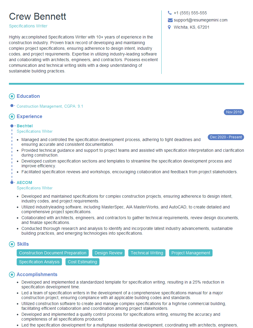
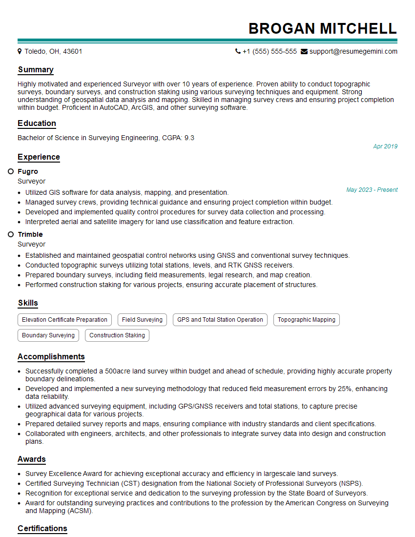
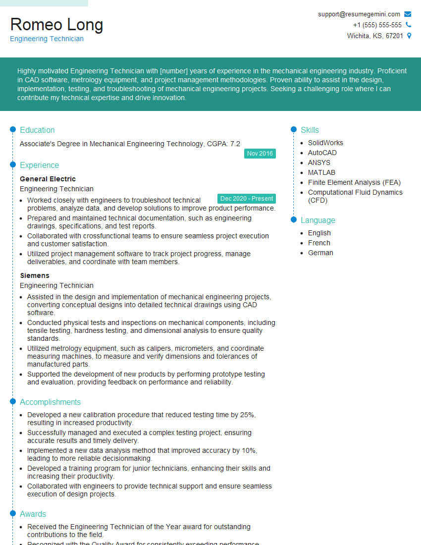
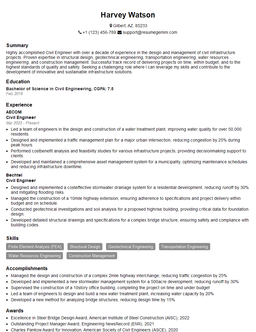
Mastering the interpretation of blueprints, technical drawings, and specifications is crucial for career advancement in engineering, architecture, and construction. A strong understanding of these skills demonstrates your attention to detail, problem-solving abilities, and technical proficiency – all highly valued attributes in the industry. To significantly increase your job prospects, focus on creating an ATS-friendly resume that highlights your relevant skills and experience. ResumeGemini is a trusted resource that can help you build a professional and effective resume tailored to the specific demands of your target roles. Examples of resumes optimized for highlighting blueprint, drawing, and specification interpretation skills are available through ResumeGemini.
Explore more articles
Users Rating of Our Blogs
Share Your Experience
We value your feedback! Please rate our content and share your thoughts (optional).
What Readers Say About Our Blog
Hi, I’m Jay, we have a few potential clients that are interested in your services, thought you might be a good fit. I’d love to talk about the details, when do you have time to talk?
Best,
Jay
Founder | CEO
