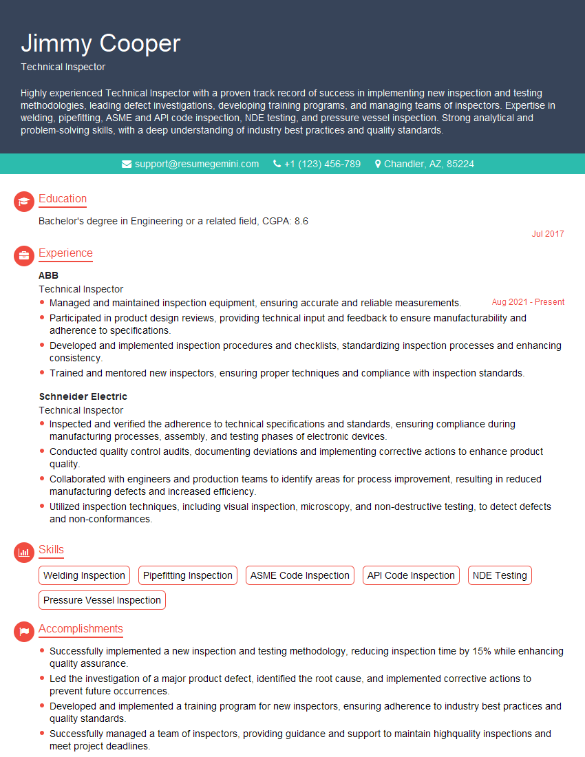
The thought of an interview can be nerve-wracking, but the right preparation can make all the difference. Explore this comprehensive guide to Measuring Tools Proficiency interview questions and gain the confidence you need to showcase your abilities and secure the role.
Questions Asked in Measuring Tools Proficiency Interview
Q 1. Explain the difference between accuracy and precision in measurement.
Accuracy and precision are two crucial aspects of measurement, often confused but distinct. Accuracy refers to how close a measurement is to the true or accepted value. Think of it like aiming for the bullseye on a dartboard – a high accuracy score means your darts are clustered near the center. Precision, on the other hand, refers to how close repeated measurements are to each other. It’s about consistency. Even if your darts aren’t hitting the bullseye, if they’re all clustered tightly together, you have high precision. You can have high precision but low accuracy (darts clustered far from the bullseye), high accuracy but low precision (darts scattered around the bullseye), high accuracy and high precision (darts clustered in the bullseye), or low accuracy and low precision (darts scattered everywhere). In a manufacturing setting, for example, producing parts with high precision ensures consistency, while high accuracy ensures the parts meet the required specifications.
Q 2. Describe the principles of uncertainty analysis in measurement.
Uncertainty analysis is the process of quantifying the uncertainty associated with a measurement. It acknowledges that no measurement is perfectly exact. Several sources contribute to this uncertainty, and understanding them is critical for reliable results. The principles involve identifying all potential sources of uncertainty (e.g., instrument limitations, environmental conditions, observer variability), quantifying each source, and then combining them to determine the overall uncertainty. This is often expressed as a confidence interval – a range of values within which the true value likely lies. For instance, measuring a length with a ruler might have an uncertainty due to the ruler’s markings (e.g., ±0.5 mm) and the observer’s ability to precisely align the ruler (±0.2 mm). Combining these using appropriate statistical methods gives the overall uncertainty of the length measurement.
Q 3. What are the common sources of measurement error?
Measurement errors can stem from various sources. These can be broadly classified into systematic errors and random errors. Systematic errors are consistent and repeatable; they always push the measurement in the same direction. Examples include instrument calibration errors (a scale consistently reads 1kg too high), environmental effects (temperature changes affecting the length of a measuring rod), or operator bias (consistent misreading of a gauge). Random errors, in contrast, are unpredictable and fluctuate from measurement to measurement. They can result from things like vibrations affecting the measurement device, small variations in the measured object, or random fluctuations in the environment. Minimizing errors involves careful instrument selection and calibration, controlled environmental conditions, proper measurement techniques, and statistical analysis of repeated measurements.
Q 4. How do you select the appropriate measuring tool for a specific task?
Choosing the right measuring tool depends on several factors: the required accuracy, the size and shape of the object being measured, the material of the object, and the cost considerations. For extremely precise measurements at the micron level, a micrometer would be appropriate. For less precise measurements, a ruler or caliper might suffice. Measuring the diameter of a small cylindrical object would require a caliper or micrometer for accurate readings, whereas measuring the length of a long rod might use a tape measure. Always consider the resolution (smallest increment) of the tool. A tool with a resolution too coarse will limit accuracy. Consider also ergonomics and ease of use: If the measurement needs to be taken in a tight space, a small digital caliper might be preferable to a larger vernier caliper.
Q 5. Explain the process of calibrating a measuring instrument.
Calibrating a measuring instrument involves comparing its readings to a known standard of higher accuracy. This ensures the instrument is providing accurate measurements. The process typically involves: (1) selecting a known standard with traceable calibration (certified by a national metrology institute or an accredited calibration laboratory), (2) following the manufacturer’s instructions for the calibration procedure, (3) making a series of measurements at different points on the instrument’s range, (4) comparing the instrument readings with the standard, and (5) documenting any discrepancies and adjusting the instrument (if possible) or applying corrections to subsequent measurements. The frequency of calibration depends on the instrument’s sensitivity, use frequency, and environmental conditions. Regular calibration ensures the instrument’s accuracy is maintained and that the measurement results are reliable.
Q 6. What are the different types of calipers and their applications?
Calipers come in various types, each suited for specific applications.
- Vernier Calipers: Provide precise measurements using a vernier scale. They’re widely used for general-purpose measurements of lengths, depths, and inside/outside diameters.
- Digital Calipers: Offer digital readout, eliminating the need for manual interpretation of the scale. They’re generally faster and easier to use than vernier calipers, but their accuracy might be slightly lower.
- Inside Calipers: Measure internal dimensions such as the diameter of a hole.
- Outside Calipers: Measure external dimensions such as the diameter of a rod or shaft.
- Depth Calipers: Measure the depth of holes or recesses.
Q 7. How do you use a micrometer to measure a diameter?
Using a micrometer to measure a diameter involves the following steps: (1) Clean both the micrometer anvil and spindle. (2) Gently place the object between the anvil and the spindle. (3) Carefully rotate the thimble until the object is lightly held, ensuring no undue force is applied. (4) Read the measurement from the micrometer’s sleeve and thimble. The sleeve indicates the larger increments, and the thimble shows the finer increments. (5) Record the reading, including the units (usually millimeters or inches). (6) Repeat the measurement several times to ensure consistency and calculate an average if needed. Remember to zero the micrometer before each use according to the manufacturer’s instructions. It’s crucial to handle micrometers carefully to avoid damaging the precision components. Accurate micrometer use requires practice and attention to detail.
Q 8. Describe the proper use of a dial indicator.
A dial indicator, also known as a dial gauge, is a precision measuring instrument used to measure small linear displacements. Proper use involves several key steps ensuring accurate readings. First, you must mount the indicator securely to a stable base, ensuring it’s perpendicular to the surface being measured. This often involves using a magnetic base or a stand. Next, zero the indicator by turning the bezel until the needle points to zero. Then, carefully contact the surface to be measured with the indicator’s contact point, avoiding any sudden movements that could damage the instrument or introduce error. Finally, take the measurement, noting the direction of movement indicated by the needle. It’s crucial to maintain consistent pressure during measurements to minimize errors. For example, checking the runout of a shaft would involve rotating the shaft slowly while monitoring the dial indicator reading. Any fluctuation indicates inconsistencies in the shaft’s roundness.
Imagine you’re measuring the gap between two precisely machined parts. A dial indicator’s high sensitivity allows you to precisely determine whether this gap is within the specified tolerance, preventing costly errors in assembly.
Q 9. What are the different types of surface finish measurement techniques?
Surface finish measurement techniques determine the texture of a surface, considering roughness, waviness, and lay. Several techniques exist, each suited to different needs and scales.
- Profilometry: This involves using a stylus to trace the surface profile and generate a three-dimensional representation. This technique is highly accurate but can be time-consuming and may damage delicate surfaces. Examples include stylus profilometers and non-contact optical profilometers (confocal microscopy).
- Optical Methods: These non-contact techniques use light to analyze the surface texture. Examples include interferometry, where light interference patterns reveal surface features, and light scattering techniques.
- Contact Methods: This includes techniques that use contact probes, such as surface roughness gauges which employ a small stylus that runs across the surface; they are simpler and faster than profilometry, but less precise for very fine features.
- Scanning Probe Microscopy (SPM): SPM techniques like Atomic Force Microscopy (AFM) offer extremely high resolution, capable of visualizing individual atoms on a surface, but they are very complex and specialized.
Choosing the right technique depends on factors like the surface material, required accuracy, and the size of the features to be measured. For example, a simple roughness gauge might suffice for checking the surface finish of a cast part, while a confocal microscope might be necessary for analyzing the micro-texture of a microchip.
Q 10. Explain the concept of gauge repeatability and reproducibility (GR&R).
Gauge Repeatability and Reproducibility (GR&R) is a statistical method used to assess the variability of a measurement system. ‘Repeatability’ refers to the variation observed when the same operator measures the same part multiple times using the same gauge. ‘Reproducibility’ refers to the variation observed when different operators measure the same part using the same gauge. A GR&R study determines how much of the total variation in measurements is due to the gauge itself versus variation in the actual parts being measured. It helps determine if a measurement system is capable of providing accurate and consistent results. The results are often expressed as a percentage of the total variation attributed to the gauge. A low percentage indicates a good measurement system.
Think of it like this: Imagine weighing a 1kg weight multiple times on the same scale. The slight variations in readings reflect the repeatability. Now, imagine several people weighing the same weight on the same scale. Variations in their readings reflect the reproducibility. A high GR&R percentage means the scale (gauge) is unreliable and contributes significantly to measurement error, obscuring the actual differences between weights (parts).
Q 11. How do you interpret a control chart for measurement data?
Control charts are graphical tools used to monitor the stability of a process over time. They plot measurement data against time, showing the central tendency and variability of the process. Common control charts include X-bar and R charts (for continuous data) and p-charts (for attribute data). Interpretation involves examining the data points to identify patterns indicative of process instability.
- Points outside control limits: Points consistently falling above or below the upper or lower control limits usually indicate an assignable cause of variation—something that needs to be investigated and corrected.
- Trends: A consistent upward or downward trend suggests a gradual shift in the process mean.
- Cycles: Regular cyclical patterns indicate that the process is influenced by periodic factors.
- Stratification: Clustering of data points suggests variation within the data.
For instance, in a manufacturing process measuring the diameter of a component, consistent points outside the control limits may indicate tool wear or a machine malfunction. Identifying these issues allows for timely corrective action, ensuring consistent product quality.
Q 12. Describe the use of statistical process control (SPC) in measurement.
Statistical Process Control (SPC) uses statistical methods to monitor and control a process to ensure consistent product quality. In measurement, SPC plays a crucial role in assessing the capability of measuring instruments, analyzing measurement data, and improving the overall measurement process. Control charts are a key component of SPC. By monitoring variation in measurement data over time, SPC helps to detect and identify issues in the measuring process, improving measurement accuracy and reducing error.
Imagine a factory producing precision bearings. Using SPC, they monitor measurements of the bearing’s inner diameter. If the control chart shows points consistently exceeding the upper control limit, it signals a potential problem with the machining process or the measuring instrument. This early detection allows for preventative maintenance or calibration to avoid producing non-conforming parts.
Q 13. What are the different types of coordinate measuring machines (CMMs)?
Coordinate Measuring Machines (CMMs) are used to accurately measure the dimensions and geometric features of three-dimensional objects. Several types exist, categorized by their design and measuring principles:
- Bridge-type CMMs: These feature a bridge-like structure moving along a linear axis, with a probe mounted on the bridge to measure points on the part. They are suitable for large workpieces.
- Gantry-type CMMs: Similar to bridge-type, but with a more robust gantry structure offering larger workspace and higher rigidity. They are commonly used in aerospace and automotive industries.
- Horizontal-arm CMMs: These feature a horizontal arm that extends to reach different positions on the part. They offer good accessibility to parts and are suited to large and complex parts.
- Articulated-arm CMMs: These are portable CMMs with flexible arms that can reach various positions; ideal for in-situ measurements and inspection of large or difficult-to-move parts.
- CMMs using different probes: Different probes provide different measurement capabilities, for example; touch probes for measuring point coordinates and scanning probes for capturing surface profiles.
The choice of CMM type depends on the size, shape, and complexity of the parts being measured, as well as budget and space constraints.
Q 14. How do you perform a CMM measurement?
Performing a CMM measurement involves several steps. First, the part is carefully fixtured on the CMM’s table, ensuring accurate and stable positioning. Next, a suitable probe is selected based on the part’s features and material. A Computer-Aided Design (CAD) model of the part is often imported into the CMM’s software to guide the measurement process. The CMM operator then programs the machine to touch specific points on the part using the probe. The CMM records the coordinates of these points, and the software uses this data to generate a report with various geometric measurements, such as distances, angles, and surface deviations. The measurements are compared against the CAD model to determine whether the part meets specifications.
For example, to measure the dimensions of a complex engine component, you would first securely clamp it to the CMM’s table, and then program a measurement routine that touches critical points, such as hole centers, edges, and surfaces. The CMM software will then calculate relevant dimensions and compare them to tolerances specified in the engineering drawings, generating a report detailing the dimensional accuracy.
Q 15. What are some common problems encountered during CMM measurement?
Common problems during CMM (Coordinate Measuring Machine) measurement often stem from a combination of factors: environmental influences, machine limitations, and operator error.
Environmental Factors: Temperature fluctuations, vibrations, and air currents can all subtly affect the accuracy of CMM measurements. Imagine trying to measure something precisely with a ruler on a windy day – the results wouldn’t be reliable. Similarly, a CMM needs a stable environment.
Machine Limitations: Even calibrated CMMs have inherent limitations in accuracy and resolution. These limitations are often specified in the machine’s technical documentation. For instance, a CMM might only be accurate to within a few micrometers, rendering it unsuitable for measuring parts requiring nanometer precision.
Operator Error: Incorrect probe selection, improper probe calibration, flawed measurement strategies, and inaccurate data entry can lead to significant errors. Just as a skilled carpenter uses the right tools correctly, a CMM operator needs proper training and adherence to established procedures. For example, incorrect probing force can deform a soft material under test leading to erroneous results.
Part Fixturing: Poorly designed fixturing or inadequate clamping can lead to inaccurate measurements due to part deformation or movement during the measurement process.
Addressing these challenges requires meticulous planning, calibration, environmental control, and rigorous operator training. Regular preventative maintenance of the CMM is also crucial.
Career Expert Tips:
- Ace those interviews! Prepare effectively by reviewing the Top 50 Most Common Interview Questions on ResumeGemini.
- Navigate your job search with confidence! Explore a wide range of Career Tips on ResumeGemini. Learn about common challenges and recommendations to overcome them.
- Craft the perfect resume! Master the Art of Resume Writing with ResumeGemini’s guide. Showcase your unique qualifications and achievements effectively.
- Don’t miss out on holiday savings! Build your dream resume with ResumeGemini’s ATS optimized templates.
Q 16. Explain the importance of traceability in measurement.
Traceability in measurement is paramount for ensuring the reliability and validity of results. It establishes a clear and unbroken chain of evidence linking a measurement to known standards. Think of it as a family tree for your measurements, tracing back to a trusted origin.
Why is this important? Without traceability, there’s no way to objectively validate the accuracy of your measurements. Imagine a company manufacturing aircraft parts—without traceability, they can’t guarantee the parts meet safety standards. If a problem arises, they can’t confidently identify the source of error.
Traceability is usually achieved through a calibration chain. Your measuring instrument is calibrated against a secondary standard, which in turn is calibrated against a primary standard traceable to a national metrology institute (like NIST in the US). This chain ensures that your measurements are ultimately linked to internationally recognized standards. Proper documentation of each step in the calibration process is key to maintaining traceability.
Q 17. What are the different standards used for measurement?
Numerous standards govern various aspects of measurement, depending on the industry and application. Some key examples include:
ISO 9001: A quality management system standard that indirectly influences measurement practices by emphasizing accuracy, traceability, and control of measuring equipment.
ISO 10012: Specifically addresses measurement management systems, providing a framework for establishing and maintaining a robust measurement process.
ASME Y14.5: This standard, commonly used in mechanical engineering, defines the principles of geometric dimensioning and tolerancing (GD&T), which dictates how dimensions and tolerances are specified on engineering drawings. It’s crucial for ensuring parts manufactured meet design specifications.
National Standards Institutes: Each country has a national standards institute (like NIST in the US or NPL in the UK) that maintains and disseminates national measurement standards. These standards form the basis of traceable measurement systems across industries.
The specific standards relevant to a given project will depend on the industry, the complexity of the parts being measured, and regulatory requirements.
Q 18. How do you handle discrepancies in measurement results?
Discrepancies in measurement results require a systematic investigation to identify the root cause. It’s not simply about discarding data; it’s about improving the measurement process. A structured approach is essential:
Repeat the measurement: Multiple measurements should always be performed to assess the repeatability of the results. Statistical analysis can then be used to determine the precision of the measurement process.
Check the equipment: Verify that the measuring instrument is properly calibrated and functioning correctly. This includes checking for any signs of damage or wear. A simple example would be checking if a micrometer’s anvil and spindle are clean and properly aligned.
Review the procedure: Ensure that the measurement procedure was followed correctly, and identify any potential sources of human error. For example, did the operator use the correct measuring technique?
Investigate environmental factors: Check the environmental conditions (temperature, humidity, vibrations) to ensure they were within acceptable limits.
Analyze the data: Use statistical methods to determine whether the discrepancies are random or systematic. Systematic errors usually indicate a problem with the equipment or procedure, whereas random errors are inherent in the measurement process.
Document findings: Maintain clear and concise records of the investigation, including the corrective actions taken to address the discrepancies.
Depending on the magnitude of the discrepancy, further investigation might involve using a different measuring instrument or involving metrology experts.
Q 19. What software do you know for metrology data analysis?
Several software packages facilitate metrology data analysis. The choice often depends on the type of measuring equipment used and the complexity of the analysis required. Some popular options include:
PolyWorks: A widely used software for inspecting and analyzing point cloud data from various measurement systems, including CMMs and laser scanners. It offers tools for surface comparison, GD&T analysis, and report generation.
PC-DMIS: A comprehensive CMM software package providing programming, measurement, and analysis capabilities. It’s known for its robust feature recognition and reporting features.
Calypso: Another popular CMM software known for its ease of use and powerful analysis tools.
Various CAD software packages: Many CAD programs incorporate metrology tools for comparing measured data with CAD models. This is essential for verifying that manufactured parts conform to the design specifications.
These software packages are generally expensive and require specialized training to use effectively.
Q 20. Describe your experience with different types of measuring tools (e.g., Vernier caliper, micrometer, optical comparator).
My experience encompasses a wide range of measuring tools, from basic instruments to advanced metrology equipment. I’m proficient with:
Vernier Calipers: I’m comfortable using vernier calipers for accurate linear measurements. I understand the importance of proper zeroing and reading the instrument correctly to minimize parallax error. I’ve used them extensively for measuring various dimensions in machined parts and ensuring they are within tolerance.
Micrometers: I have significant experience using micrometers for precise measurements, down to micrometer levels. I know how to select the appropriate micrometer based on the part’s size and material. I understand how to interpret the readings and account for any inherent measurement uncertainty.
Optical Comparators: I’ve used optical comparators to measure the profiles of parts, to detect surface imperfections and to verify that dimensions and features are within specified tolerances. I’m familiar with various techniques for aligning the part and interpreting the projected image.
CMMs (Coordinate Measuring Machines): I have substantial experience operating and programming CMMs for detailed 3D measurements of complex parts. I’m familiar with different probe types, measurement strategies, and data analysis techniques. This includes using CMM software to create measurement routines, analyze results, and generate reports.
My experience goes beyond just using these tools; it also includes understanding their limitations, calibration procedures, and the best practices for ensuring accurate and reliable measurements.
Q 21. Explain your understanding of tolerance and its importance in manufacturing.
Tolerance represents the permissible variation in a dimension or a feature of a part. It’s the acceptable range of deviation from a nominal (ideal) value. Imagine ordering a custom-made shirt – you’d specify your size, but there’s a tolerance built-in because an exact fit isn’t always possible. The tolerance defines the acceptable range of sizes that would still be considered satisfactory.
In manufacturing, tolerance is crucial for several reasons:
Functional requirements: Parts must be within tolerance to function correctly. A slightly larger or smaller hole in a machine component could prevent it from working as designed.
Interchangeability: Tolerance ensures that parts manufactured at different times or locations can be interchanged without sacrificing functionality.
Cost-effectiveness: Stricter tolerances generally increase manufacturing costs. Engineers carefully select appropriate tolerances to balance functionality and cost.
Quality control: Tolerance is fundamental to quality control processes. It provides quantifiable criteria for acceptance or rejection of parts during inspection. Parts outside the tolerance range are considered defective.
Understanding and specifying tolerances appropriately is a core skill for engineers and metrologists. Incorrectly specified tolerances can lead to increased costs (due to overly tight tolerances) or functional failures (due to overly loose tolerances).
Q 22. How do you ensure the accuracy of your measurements?
Ensuring accurate measurements is paramount in any precision-based field. It’s a multi-faceted process that begins before the measurement even starts and continues through to data analysis. My approach involves a combination of meticulous instrument calibration, proper technique, and diligent error analysis.
Calibration: Before any measurement, I verify that my instruments are calibrated according to the manufacturer’s specifications and traceable to national or international standards. This often involves using certified reference standards to check for accuracy and drift. For example, I regularly calibrate my micrometers against a calibrated gauge block set.
Proper Technique: Correct handling and usage of the instrument are critical. This includes understanding the instrument’s limitations, avoiding parallax errors (errors due to incorrect viewing angle), and maintaining a consistent measurement technique. For instance, when using a caliper, I ensure I’m applying consistent pressure to avoid compression errors.
Environmental Factors: Temperature, humidity, and even vibrations can affect measurement accuracy. I account for these factors by using instruments suitable for the environment and by taking measurements under controlled conditions whenever possible. If measuring a long length of metal, I’d be aware of thermal expansion.
Error Analysis: No measurement is perfect. I always consider potential sources of error – systematic (consistent errors), random (unpredictable errors), and human error – and attempt to minimize their impact. Repeating measurements and calculating the mean helps to reduce the impact of random errors.
Q 23. Describe a situation where you had to troubleshoot a measurement problem.
During a project involving the precision machining of aircraft components, we encountered inconsistencies in the measurements of a crucial part using our coordinate measuring machine (CMM). Initial measurements showed variations beyond acceptable tolerances.
Our troubleshooting involved a systematic approach:
Recalibration: We first recalibrated the CMM using certified artifacts and checked its software for any bugs.
Environmental Checks: We checked the temperature and humidity levels in the CMM’s environment as these can impact accuracy.
Probe Check: The CMM’s probe was examined for wear and tear and replaced as a precaution.
Measurement Technique Review: We reviewed the measurement routines and fixturing to eliminate any potential human error or errors in the setup.
Part Analysis: Finally, we rigorously inspected the part itself for any defects or inconsistencies that could be skewing measurements.
Through this process, we identified a slight misalignment in the CMM’s probe. Adjusting the alignment and repeating the measurements solved the problem, and the parts passed inspection.
Q 24. What is your experience with different types of measurement systems?
My experience encompasses a wide range of measurement systems, from basic hand tools to sophisticated computer-controlled equipment.
Hand Tools: I’m proficient in using calipers (vernier and digital), micrometers, rulers, depth gauges, and dial indicators. I understand their limitations and the importance of proper technique with each.
Optical Systems: I have experience using optical comparators for precise dimensional checks and surface finish analysis. I understand the principles of optical magnification and its applications in metrology.
Coordinate Measuring Machines (CMMs): I’m experienced in operating and programming CMMs, which use touch probes or laser scanners to obtain three-dimensional measurements. My experience includes various types like bridge-type, cantilever type and gantry-type CMM’s.
Laser Scanners: I have utilized laser scanners for both static and dynamic measurement applications, including 3D surface scanning and reverse engineering.
Digital Image Correlation (DIC): I have experience with advanced optical measurement systems like Digital Image Correlation (DIC) for strain measurement and deformation analysis.
Q 25. How do you maintain and care for measuring instruments?
Maintaining measuring instruments is crucial for accuracy and longevity. My approach combines regular cleaning, careful storage, and periodic calibration.
Cleaning: I regularly clean instruments using appropriate solvents and soft cloths to remove dust, debris, and any residue. I avoid harsh chemicals that might damage the instrument’s surfaces or internal mechanisms. For example, I use compressed air to remove debris from micrometer threads.
Storage: Instruments are stored in their designated cases or containers, protected from dust, moisture, and extreme temperatures. I also avoid stacking instruments to prevent damage.
Calibration: Regular calibration (frequency depends on the instrument and its use) is essential to ensure accuracy. I maintain detailed records of all calibrations, tracking any drift and correcting as needed.
Preventive Maintenance: I perform basic preventative maintenance tasks like lubricating moving parts (according to manufacturer instructions) to ensure smooth operation and prevent wear.
Q 26. Explain your experience with data acquisition and analysis software.
I’m proficient in several data acquisition and analysis software packages. My experience includes:
CMM Software: I’m familiar with various CMM software packages used for programming measurement routines, data acquisition, and report generation. This includes PCDMIS, Calypso, and Polyworks.
Spreadsheet Software: I use spreadsheet software (e.g., Microsoft Excel) for data organization, statistical analysis (calculating mean, standard deviation, etc.), and generating charts and graphs to visualize measurement results.
Statistical Process Control (SPC) Software: I have used SPC software to monitor and analyze measurement data, identifying trends and detecting out-of-control conditions, using control charts like X-bar and R charts.
Programming Languages: I have basic programming skills (e.g., Python) which I use to automate data processing tasks and create custom analysis tools.
I understand the importance of data integrity and use appropriate methods to ensure data accuracy and traceability throughout the entire process.
Q 27. Describe your experience with different types of inspection techniques.
My experience with inspection techniques includes a variety of both destructive and non-destructive methods:
Dimensional Inspection: This is my core expertise, utilizing various measuring tools and CMMs to check part dimensions against specifications.
Visual Inspection: This involves carefully examining parts for surface defects such as scratches, cracks, or pitting. Often using magnification tools.
Non-Destructive Testing (NDT): I have some experience with NDT methods such as liquid penetrant inspection (for surface cracks) and magnetic particle inspection (for subsurface defects in ferromagnetic materials).
Destructive Testing: While less frequently used, I’m familiar with destructive testing methods such as tensile testing and hardness testing, typically performed in a lab setting for material characterization.
The choice of inspection technique always depends on the specific requirements of the part and the application.
Q 28. What are your strengths and weaknesses in using measuring tools?
My strengths lie in my methodical approach to measurement, my understanding of various measurement systems and my proficiency in data analysis. I am detail-oriented and strive for accuracy. I am also comfortable using advanced software for data acquisition and analysis.
One area for improvement is expanding my knowledge of advanced NDT techniques, particularly those involving ultrasonic testing or X-ray inspection. I am actively seeking opportunities to enhance my proficiency in these areas through training and on-the-job experience.
Key Topics to Learn for Measuring Tools Proficiency Interview
- Understanding Measurement Units and Systems: Mastering the conversion between metric (SI) and imperial units, and understanding the implications of accuracy and precision in different systems.
- Calipers and Micrometers: Learn the operation, reading, and maintenance of both Vernier calipers and micrometers. Practice taking accurate measurements and understanding the limitations of each tool.
- Dial Indicators and Gauges: Familiarize yourself with different types of dial indicators and their applications in measuring surface irregularities, runout, and other dimensional variations. Understand how to interpret dial gauge readings accurately.
- Levels and Alignment Tools: Grasp the principles behind level measurements and how to use various tools to ensure proper alignment and leveling in various applications (e.g., machining, construction).
- Digital Measuring Instruments: Explore the functionalities and applications of digital measuring tools, including their advantages and limitations compared to traditional methods. Understand the importance of calibration and data logging.
- Measurement Error Analysis: Develop a strong understanding of potential sources of error in measurements, including systematic and random errors. Learn techniques for minimizing measurement uncertainty and improving accuracy.
- Practical Applications and Case Studies: Think about real-world scenarios where measuring tools are critical. Consider examples from your own experience or research specific industry applications to demonstrate your problem-solving abilities.
- Troubleshooting and Calibration: Be prepared to discuss troubleshooting common issues with measuring tools and understanding the importance of regular calibration to maintain accuracy and precision.
Next Steps
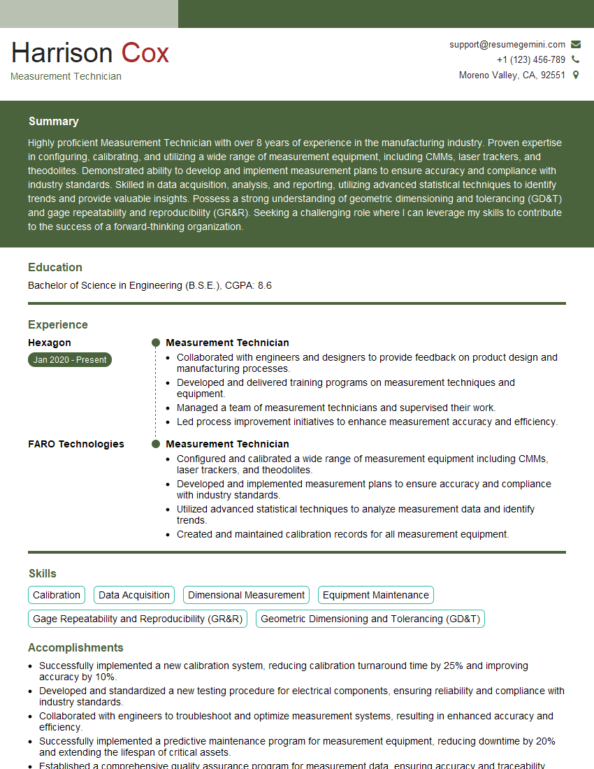
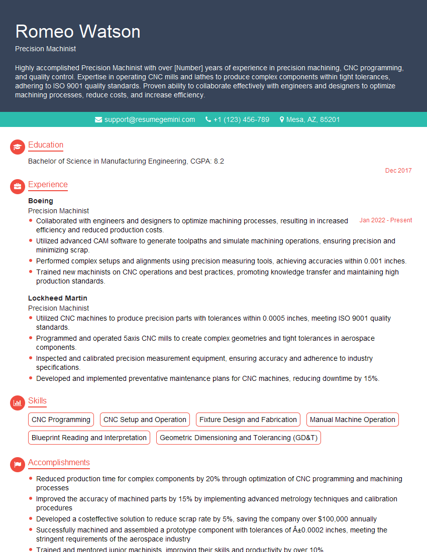
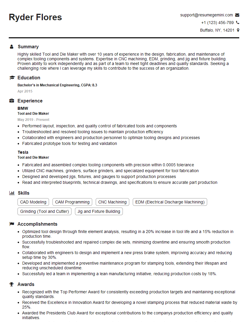
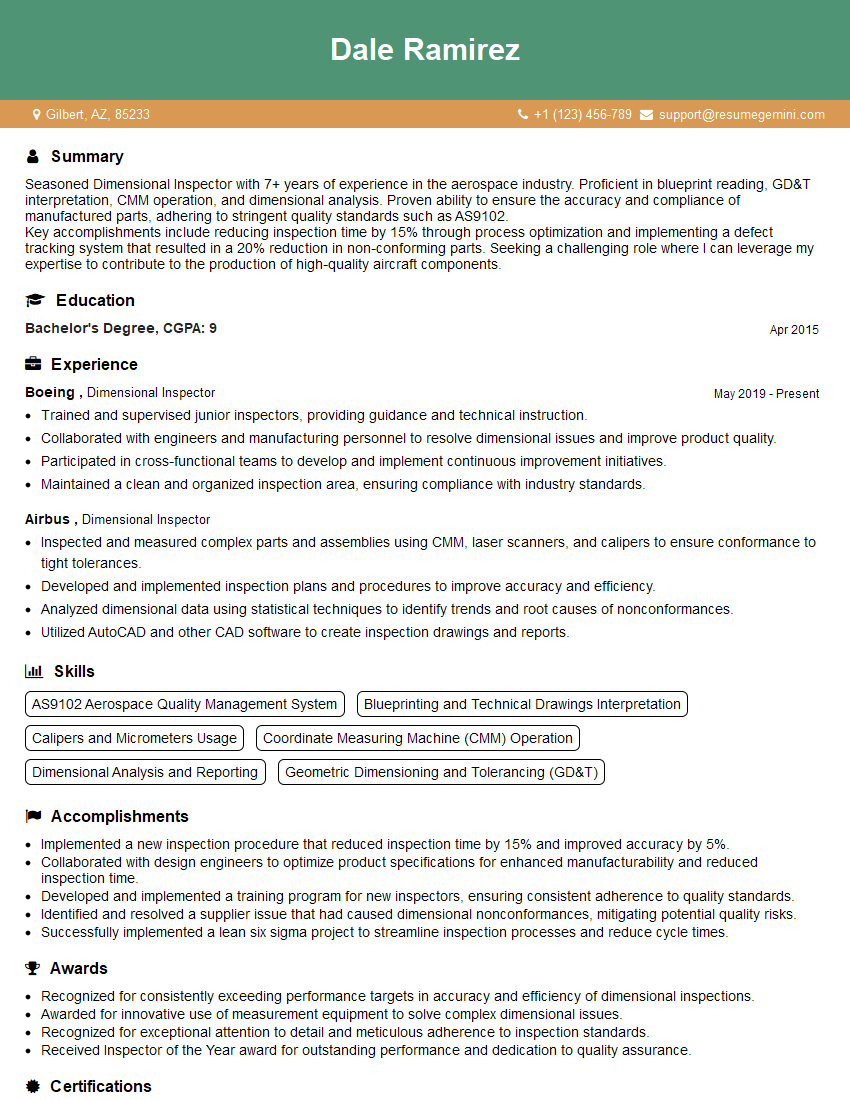
Mastering Measuring Tools Proficiency is crucial for career advancement in many technical fields, opening doors to higher-paying roles and greater responsibility. A well-crafted resume is your key to unlocking these opportunities. Creating an ATS-friendly resume is essential to ensure your application gets noticed by recruiters. ResumeGemini can help you build a professional, impactful resume that highlights your skills and experience effectively. We offer examples of resumes tailored to Measuring Tools Proficiency to guide you in showcasing your expertise. Let ResumeGemini help you land your dream job!
Explore more articles
Users Rating of Our Blogs
Share Your Experience
We value your feedback! Please rate our content and share your thoughts (optional).
What Readers Say About Our Blog
Hi, I’m Jay, we have a few potential clients that are interested in your services, thought you might be a good fit. I’d love to talk about the details, when do you have time to talk?
Best,
Jay
Founder | CEO
