Feeling uncertain about what to expect in your upcoming interview? We’ve got you covered! This blog highlights the most important SolidWorks or CAD/CAM Software interview questions and provides actionable advice to help you stand out as the ideal candidate. Let’s pave the way for your success.
Questions Asked in SolidWorks or CAD/CAM Software Interview
Q 1. Explain the difference between a part, assembly, and drawing in SolidWorks.
In SolidWorks, a part, assembly, and drawing represent distinct stages of the design process. Think of it like building a house: the part is a single brick, the assembly is the entire house constructed from many bricks, and the drawing is the blueprint showing how it’s all put together.
Part: A part is a single, independent 3D model. It’s the fundamental building block in SolidWorks. Imagine designing a gear; that individual gear would be a part. You define its geometry using various features (extrude, revolve, etc.).
Assembly: An assembly is a collection of multiple parts combined to create a more complex model. Our house example fits perfectly here; it combines many individual bricks (parts) to form a complete structure (assembly). You can constrain the parts within an assembly to define their relative positions and movements.
Drawing: A drawing is a 2D representation of a part or assembly. It’s essentially a detailed plan showing dimensions, tolerances, materials, and other manufacturing information. This is like the blueprint of our house; it shows everything a builder needs to know to construct the building accurately.
To reiterate, a part is the single component, an assembly is the combination of parts, and a drawing is the 2D representation for manufacturing or communication.
Q 2. Describe your experience with different CAD modeling techniques (e.g., extrude, revolve, sweep).
I have extensive experience with various CAD modeling techniques in SolidWorks. My expertise includes the core features and their advanced applications.
Extrude: This creates a 3D solid by sweeping a 2D profile along a specified path, typically a straight line. I’ve used this extensively for creating simple prismatic shapes, such as blocks and housings. For instance, I designed a custom enclosure for a circuit board using an extruded profile of the board’s outline.
Revolve: This generates a solid of revolution by rotating a 2D profile around an axis. This is perfect for creating symmetrical parts like cups, gears, and shafts. I recently utilized this to model a custom pump impeller, precisely defining its vanes and central hub.
Sweep: This technique is more complex, allowing you to create a 3D solid by sweeping a 2D profile along a 3D path. This offers great flexibility for complex shapes. I applied this when designing a curved duct for an air-handling system, efficiently shaping the airflow path.
Other techniques: My skills also extend to other essential techniques like lofting, shell, and pattern features, allowing me to create a wide variety of complex geometries.
Selecting the right technique is crucial for efficiency and accuracy. Understanding the limitations and capabilities of each method allows for optimized design and manufacturing.
Q 3. How do you manage large assemblies in SolidWorks?
Managing large assemblies efficiently in SolidWorks is critical for productivity. My strategies include a combination of techniques:
Component simplification: Before assembling, I strive to simplify individual components where possible. This reduces file sizes and improves performance. This often involves using simplified representations for less critical components.
Lightweight components: For large assemblies, I utilize lightweight components to reduce the computational load. This creates simplified representations of parts without losing essential design information for visualization and manipulation.
Sub-assemblies: I frequently break down large assemblies into smaller, manageable sub-assemblies. This greatly improves performance, allowing easier management and modification of individual sections.
Top-down design approach: I generally prefer a top-down approach, starting with the overall assembly and adding sub-assemblies and parts. This ensures better organization and reduces assembly errors.
Component suppression: When working with massive assemblies, I use component suppression to temporarily hide less relevant parts and improve performance during manipulation.
In essence, efficient management is achieved through a combination of thoughtful component design, strategic assembly organization, and leveraging SolidWorks’ inherent tools for managing complexity. It’s a combination of design practice and feature usage.
Q 4. Explain your experience with feature-based modeling.
Feature-based modeling is the cornerstone of SolidWorks. It’s a parametric modeling technique where you create a 3D model by adding or subtracting features (extrusions, revolves, cuts, etc.) sequentially. Each feature retains its own parameters, allowing for easy modifications later in the design process.
My experience includes leveraging this to create extremely detailed and complex parts. I can easily go back and alter the dimensions of an earlier feature without having to manually adjust the entire geometry. This parametric approach is invaluable for design iteration and optimization. For instance, I designed a complex injection-molded part, where altering the wall thickness required only changing a single parameter in the initial extrusion feature; the entire model updated automatically, saving significant time and effort.
This approach also provides better design control, making it ideal for manufacturing since changes are easily tracked and updated across the design.
Q 5. How do you create and manage design tables in SolidWorks?
Design tables in SolidWorks are powerful tools for creating families of parts and managing design variations. They allow you to define multiple parameters (dimensions, materials, etc.) within a table, and SolidWorks automatically generates variations of the part based on the table’s data.
I’ve used design tables extensively to create families of parts with different sizes and configurations. For example, when designing a series of fasteners, I created a design table with columns for diameter, length, and thread pitch. SolidWorks then automatically generated numerous fastener variations based on the combinations specified in the table. This saved an enormous amount of time compared to manually creating each part individually. Effectively managing these tables ensures design consistency and facilitates rapid prototyping.
Managing these tables involves careful planning of the parameters included. Clear naming conventions are also crucial for efficient management and prevent errors in automation. Using formulas within the tables also allows for creating complex parameter relationships.
Q 6. Describe your experience with SolidWorks Simulation.
My experience with SolidWorks Simulation encompasses a wide range of analysis types including static, dynamic, and fatigue analysis. I’m proficient in applying these tools to verify the structural integrity and performance of designs under various loads and conditions.
I’ve used SolidWorks Simulation to analyze the stress and deformation in a variety of components, from simple brackets to complex assemblies. For example, I used it to analyze the stress on a custom bracket under extreme load conditions. The simulation helped to identify areas of potential failure, allowing me to optimize the design and ensure its structural integrity. Such simulations allow for risk mitigation and avoidance of costly failures during the manufacturing and operation stages.
Beyond structural analysis, I’ve also leveraged simulation for thermal studies, predicting temperature distributions and optimizing heat dissipation. This is particularly valuable when designing electronics enclosures or components with high heat generation.
Q 7. Explain your understanding of GD&T (Geometric Dimensioning and Tolerancing).
Geometric Dimensioning and Tolerancing (GD&T) is a system for defining and communicating engineering tolerances on technical drawings. It’s crucial for ensuring parts fit together correctly and function as intended.
My understanding of GD&T includes applying symbols and notations to precisely define tolerances. This goes beyond simple dimensional tolerances, specifying form, orientation, location, and runout. For instance, I used GD&T to specify the permissible variations in the position and orientation of a critical mating feature. This ensures that parts will assemble correctly, even with manufacturing variations. Such precise control is vital in high-precision engineering.
Using GD&T correctly is about clear communication. It ensures that the manufacturing process produces parts that meet the design intent, reducing ambiguity and preventing costly rework or manufacturing issues. It’s essential for effective collaboration between design and manufacturing teams.
Q 8. How do you handle design changes and revisions in SolidWorks?
Handling design changes and revisions in SolidWorks is crucial for efficient project management and collaboration. My approach involves leveraging SolidWorks’ built-in revision control features and adhering to a structured workflow. This typically begins with establishing a baseline design. Subsequent changes are managed through creating new configurations or using SolidWorks’ Revision Table feature. This allows for the comparison of different design iterations, tracking changes made, and easily reverting to previous versions if necessary. For example, if I’m designing a part and need to adjust its dimensions, I’d create a new configuration, rename it to reflect the change (e.g., ‘Revision A,’ ‘Revision B’), and document the modifications in the Revision Table. This ensures a clear audit trail, facilitating collaboration and preventing design conflicts when working in a team environment. Furthermore, I utilize SolidWorks’ ‘Design History’ feature to track and manage design changes over time, providing a chronological record of modifications to the model.
Beyond SolidWorks’ built-in features, I also implement a robust file management system, often incorporating a version control system like Vault or similar software, to ensure multiple team members can access and modify files without data loss or conflicts. This system ensures all team members work with the latest approved version of the design.
Q 9. What are your preferred methods for creating detailed drawings?
Creating detailed drawings in SolidWorks involves a structured process focused on clarity, accuracy, and completeness. I begin by ensuring the 3D model is fully detailed and contains all necessary features. Then, I leverage SolidWorks’ drawing tools to create orthographic views, sectional views, and detailed annotations. I prioritize using standard drafting practices and company-specific templates to maintain consistency and clarity. For instance, I ensure all dimensions are clearly indicated, utilizing appropriate dimensioning techniques and adhering to tolerance specifications. I also include notes, material specifications, surface finish callouts, and any other relevant information to make the drawing comprehensive. Creating a high-quality drawing is about more than just visual representation; it’s about providing all the necessary information for manufacturing. A well-made drawing should leave no room for ambiguity or misinterpretation.
I often utilize SolidWorks’ automated drawing features, such as automatic dimensioning and ballooning, to increase efficiency and reduce the chance of human error. Finally, I always perform a thorough review of the completed drawing to ensure accuracy and completeness before releasing it for manufacturing.
Q 10. Describe your experience with CAM software (e.g., Mastercam, FeatureCAM).
My experience with CAM software, specifically Mastercam, spans several years and encompasses a wide range of applications. I’m proficient in creating toolpaths for various machining operations, including milling, turning, and wire EDM. I’ve used Mastercam to program complex parts with intricate features, optimizing toolpaths for both speed and surface finish. For instance, I’ve utilized Mastercam’s dynamic milling strategies to generate efficient toolpaths for 3D surfaces, minimizing machining time and maximizing tool life. I’m also comfortable with the software’s post-processing capabilities, configuring post-processors for various CNC machines to ensure accurate code generation.
One project that stands out involved creating the toolpaths for a highly complex aerospace part requiring several different milling operations. Using Mastercam’s simulation features, I was able to identify and resolve potential collisions and optimize the toolpaths to minimize machining time, leading to significant cost savings for the project. My experience also extends to working with different types of materials and understanding the implications of material properties on tool selection and machining parameters. I’m well-versed in strategies for handling different materials’ hardness and machinability to produce high-quality results.
Q 11. Explain the process of generating CNC toolpaths.
Generating CNC toolpaths is a multi-step process that requires a good understanding of both CAD and CAM principles. It begins with importing the CAD model into the CAM software. Next, I define the machining operations required to manufacture the part. This might involve selecting different milling strategies (e.g., roughing, finishing, pocketing), defining stock material, and choosing appropriate cutting tools. Once the machining operations are defined, I use the CAM software’s toolpath generation features to create the actual toolpaths. This process involves specifying parameters such as feed rate, spindle speed, depth of cut, and step-over. The software calculates the precise movements required for the CNC machine to accurately manufacture the part based on these parameters.
After the toolpaths are generated, I always perform a thorough simulation to verify that the toolpaths are correct and free from collisions. This simulation step helps to prevent potential damage to the machine or the workpiece. Finally, I generate the CNC code (G-code) using a post-processor that is compatible with the specific CNC machine being used. The post-processor translates the toolpaths into a format that the CNC machine can understand and execute.
Q 12. How do you optimize toolpaths for efficiency and surface finish?
Optimizing toolpaths for efficiency and surface finish is crucial for minimizing machining time, extending tool life, and achieving the desired quality. Several strategies are employed to achieve this. For efficiency, I focus on optimizing parameters such as feed rate and depth of cut. Higher feed rates generally reduce machining time, but excessive speeds can lead to tool breakage or poor surface finish. Similarly, optimizing the depth of cut minimizes the number of passes required to remove material. Strategic use of different cutting tools (roughing and finishing) can also greatly improve efficiency. Roughing tools are designed to quickly remove large amounts of material, while finishing tools produce a high-quality surface finish.
For surface finish, I employ strategies like reducing the step-over distance and using appropriate finishing strategies. Smaller step-over creates smoother surfaces, but it also increases machining time. Balancing efficiency and surface quality is key. Furthermore, I select appropriate cutting tools with sharp cutting edges and optimize the spindle speed to avoid excessive heat buildup, which can negatively impact surface finish. Careful consideration of toolpath strategies, such as using helical toolpaths for smoother transitions between passes, significantly improves the final surface quality. It’s a delicate balancing act: efficient toolpaths don’t always equate to the best surface finish, so iterative adjustments are necessary to achieve the optimal balance.
Q 13. What are your experiences with different post-processors?
My experience with post-processors is extensive. Post-processors are crucial for generating accurate and machine-specific CNC code. I’ve worked with various post-processors for different CNC machines from different manufacturers. Each post-processor requires a different configuration to ensure the generated code is compatible with the specific machine’s control system. I’m familiar with configuring post-processors to control aspects like tool changes, coolant activation, spindle speed, and feed rates. Incorrect configuration can lead to machine errors or incorrect part machining. Therefore, a deep understanding of the CNC machine and its control system is necessary.
The selection of the right post-processor is crucial to ensure that the generated G-code accurately reflects the toolpaths created in the CAM software. Inconsistencies can result in wasted material, damaged tools, or an incorrectly machined part. I’ve encountered situations where using an incorrect post-processor resulted in unexpected tool movements or errors, highlighting the importance of careful selection and verification.
Q 14. Describe your experience with different machining processes (e.g., milling, turning).
My experience encompasses a wide range of machining processes, including milling and turning. Milling involves removing material from a workpiece using a rotating cutter, capable of creating a variety of shapes and features. I’m proficient in various milling techniques, including face milling, end milling, and profile milling. Different milling techniques are selected based on the specific geometry and material of the workpiece. For example, roughing cuts use high-speed, high-feed milling to remove large amounts of material quickly, whereas finishing cuts use finer tools and smaller step-overs to achieve a smooth surface finish.
Turning is a subtractive manufacturing process used to create cylindrical parts by rotating a workpiece while a cutting tool removes material. I have extensive experience in turning operations such as facing, turning, grooving, and threading. I understand the relationships between cutting parameters, tool geometry, and material properties in both milling and turning. This allows me to select the optimal cutting conditions to ensure efficient material removal, high surface quality, and extended tool life. The knowledge of these different processes and their applications allows for informed decisions in selecting the best manufacturing approach for any project.
Q 15. How do you troubleshoot errors during CNC machining?
Troubleshooting CNC machining errors is a systematic process that involves careful observation, analysis, and iterative adjustments. Think of it like detective work – you need to gather clues to pinpoint the culprit.
My approach begins with a thorough review of the G-code program. I look for syntax errors, toolpath inconsistencies, or unexpected rapid movements that could cause collisions or inaccurate cuts. For instance, a missing ‘G00’ command for a rapid traverse or an incorrect spindle speed could lead to poor surface finish or even machine damage. I’ll often use a G-code simulator to visually inspect the toolpath before sending it to the machine.
Next, I examine the machine setup. This includes verifying the workholding (is the workpiece securely clamped?), the tool selection (is the correct tool used and is it sharp enough?), and the machine’s zero point (is the machine correctly referenced to the workpiece?). A misaligned workpiece or a dull tool can easily lead to dimensional errors.
If the issue persists, I’ll investigate the material properties. Is the material harder or softer than expected? Is there internal stress or inconsistent density within the material? These factors can dramatically affect the machining process. I’ll also check for environmental conditions such as temperature variations that could affect the material or machine performance.
Finally, I meticulously document all my findings and corrective actions, creating a detailed record for future reference and improvement. This systematic approach ensures that I effectively diagnose and solve CNC machining errors, minimizing downtime and maximizing efficiency.
Career Expert Tips:
- Ace those interviews! Prepare effectively by reviewing the Top 50 Most Common Interview Questions on ResumeGemini.
- Navigate your job search with confidence! Explore a wide range of Career Tips on ResumeGemini. Learn about common challenges and recommendations to overcome them.
- Craft the perfect resume! Master the Art of Resume Writing with ResumeGemini’s guide. Showcase your unique qualifications and achievements effectively.
- Don’t miss out on holiday savings! Build your dream resume with ResumeGemini’s ATS optimized templates.
Q 16. How familiar are you with different file formats (e.g., STEP, IGES, DXF)?
I’m proficient with various CAD file formats, including STEP, IGES, DXF, and SolidWorks native files (.sldprt, .sldasm). Each format serves a unique purpose, and understanding their strengths and weaknesses is crucial for smooth data exchange.
STEP (Standard for the Exchange of Product data) is an industry-neutral format ideal for transferring complex 3D models between different CAD systems. It maintains a high level of geometric fidelity. Think of it as a universal language for CAD.
IGES (Initial Graphics Exchange Specification) is similar to STEP but is somewhat older and less robust for complex designs. It is also an industry standard, but STEP is generally preferred for modern applications.
DXF (Drawing Exchange Format) is primarily used for 2D drawings and can also contain some 3D information, though it is not as feature-rich as STEP or IGES. DXF is commonly used for simpler designs or when collaborating with less sophisticated CAD systems.
My experience includes converting and repairing files between these formats, addressing inconsistencies or data loss that can occur during conversion. I understand the nuances of each format and select the appropriate one based on the project requirements and software compatibility.
Q 17. Describe your experience with data management systems.
My experience with data management systems encompasses both cloud-based solutions like Autodesk Vault and local network-based systems. Effective data management is paramount for collaborative projects, ensuring version control, preventing data loss, and streamlining workflows.
In previous roles, I’ve utilized PDM (Product Data Management) systems to manage revisions of CAD models, drawings, and associated documentation. These systems allow multiple team members to access and modify files concurrently while tracking changes and preventing accidental overwrites. This is particularly crucial in larger projects with multiple engineers involved.
For instance, I’ve worked with systems that incorporate automated workflows for approvals, check-in/check-out processes, and revision tracking. This structured approach ensures data integrity and accountability, which is essential in a professional manufacturing environment. My understanding also covers the implementation of proper file naming conventions and directory structures to maintain an organized data repository.
Q 18. Explain your understanding of tolerance stack-up analysis.
Tolerance stack-up analysis is a critical process in engineering design that accounts for how individual component tolerances accumulate to impact the overall assembly dimensions. Imagine building a house – each brick has a tolerance, and if you don’t account for these small variations, the entire structure could be misaligned.
In simpler terms, it is the prediction of the variation in a final dimension caused by the variations in the individual dimensions of its components. This analysis is crucial to ensure the final product meets its design specifications.
My experience includes using both worst-case and statistical methods for tolerance stack-up analysis. Worst-case analysis assumes all tolerances are additive in their worst-possible combination, providing a conservative estimate of the overall variation. Statistical methods, on the other hand, consider the statistical distribution of individual tolerances and provide a more probabilistic assessment, often revealing a smaller overall variation.
I’m proficient in using tools like SolidWorks Tolerance Analysis to perform these analyses, allowing me to identify potential issues early in the design process, optimizing designs for manufacturability and reducing the risk of assembly problems. This ensures that the final product reliably meets specifications.
Q 19. How do you ensure the accuracy and quality of your designs?
Ensuring accuracy and quality in my designs is a multi-faceted process starting even before the modeling phase. It’s about diligent planning and employing various verification methods.
Design Review: I always conduct thorough design reviews with colleagues, leveraging their expertise to catch potential flaws or areas for improvement that I might have missed. A fresh pair of eyes often spots things you don’t.
Model Checks: I utilize SolidWorks’ built-in tools to perform model checks for interference, over-constraints, and other geometrical inconsistencies. Think of this as spell-checking your design before it goes to production. These features ensure that the model is geometrically sound before proceeding.
Simulation: For critical components, I employ simulations (FEA, as discussed below) to validate the design under realistic operating conditions, ensuring that it can withstand the intended stresses and loads. This is critical to prevent failures or unexpected behavior.
Prototyping: When appropriate, I create physical prototypes to validate the design and identify any unforeseen issues before committing to full-scale production. A physical prototype allows for tangible evaluation, often revealing aspects that are impossible to identify through simulations alone.
GD&T (Geometric Dimensioning and Tolerancing): I diligently apply GD&T to define the required tolerances and geometric controls on the drawing, ensuring that the design intent is clearly communicated to the manufacturing team and that the parts will assemble correctly.
Q 20. Describe your experience with FEA (Finite Element Analysis).
I possess significant experience with Finite Element Analysis (FEA), using it to predict the structural behavior of components under various load conditions. FEA is like a virtual test lab, allowing us to evaluate a design’s performance without building expensive physical prototypes.
My experience spans various FEA software packages, including SolidWorks Simulation. I’m proficient in defining material properties, meshing techniques, and boundary conditions to accurately model real-world scenarios. I can use FEA to analyze stress, strain, displacement, and other critical factors for mechanical components. This allows for a deeper understanding of how the design will react under different scenarios (forces, pressures, temperature) leading to informed design modification decisions.
For instance, I’ve used FEA to optimize the design of a bracket to withstand a specific load, ensuring it meets safety standards without excessive weight. Another example would be using FEA to analyze the thermal performance of an electronic enclosure to ensure proper heat dissipation. FEA is an essential tool for ensuring design robustness and reliability.
Q 21. What is your experience with parametric modeling?
Parametric modeling is the cornerstone of my CAD workflow. It’s a way of creating designs where dimensions and features are defined by parameters, allowing for easy modification and iteration. Think of it as creating a design with adjustable sliders instead of fixed values.
In SolidWorks, I extensively use parametric modeling techniques to build highly flexible and modifiable designs. Changing a single parameter, like the length of a component, automatically updates all related features, saving significant time and effort. For example, if I design a part with a specific diameter and length, altering the diameter will automatically adjust other aspects dependent on the diameter, such as the overall part volume or the size of related features.
This approach is particularly beneficial when exploring design alternatives or making design changes later in the process. For example, I may design a family of products, all sharing a similar base design but with varying dimensions or features. By using parameters, I can easily generate variations, leading to increased efficiency and cost savings.
My proficiency in parametric modeling extends to the creation of design tables, which allow for automating the generation of multiple variations based on different parameter sets. This is crucial for producing a range of similar products with subtle differences quickly and efficiently.
Q 22. How do you utilize SolidWorks’ assembly constraints effectively?
Effective assembly constraint usage in SolidWorks is crucial for creating robust and functional assemblies. It’s about defining how parts interact and move relative to each other. Think of it like building with LEGOs – you need to connect the bricks correctly to get the desired structure.
SolidWorks offers a variety of constraints, including:
- Mate constraints: These define fixed relationships, like aligning faces, concentric cylinders, or inserting one part into another (e.g., a screw into a hole). For instance, using a ‘Flush’ mate ensures two faces are perfectly aligned.
- Insert constraints: Specifically for inserting cylindrical parts into holes, ensuring proper fit and preventing unwanted movement.
- Distance constraints: Set a precise distance between two points or faces. This is useful for controlling spacing or gaps.
- Angle constraints: Control the angular relationship between two faces or edges, useful for positioning parts at specific angles.
- Symmetry constraints: Enforce symmetry around a plane, ensuring mirrored parts align correctly.
A well-constrained assembly is crucial to avoid over-constraints (where parts are too tightly defined leading to assembly errors) or under-constraints (where parts have excessive freedom of movement). I always aim for a fully defined, yet flexible enough, assembly using a structured approach, starting with the key components and working outward. For complex assemblies, I utilize component patterns and configurations effectively, applying appropriate constraints to each instance for consistency.
For example, during the design of a robotic arm, I might use mate constraints to connect the individual links, ensuring precise joint movement while leveraging distance and angle constraints to define the desired range of motion.
Q 23. Explain your experience working with different materials in CAD/CAM.
My experience spans a range of materials, from common plastics and metals to composites and specialized alloys. Understanding material properties is essential for successful CAD/CAM workflow. Each material behaves differently during machining; therefore, selection heavily influences the design and manufacturing process.
For instance, when designing a part for injection molding (using ABS plastic), I would consider factors like shrinkage, draft angles, and wall thickness to ensure successful molding. Conversely, when working with aluminum for CNC machining, I’d optimize the design for efficient material removal, considering toolpath strategies and potential for chatter (vibration). I use SolidWorks’ material library extensively to specify material properties which automatically populate density, Young’s Modulus, etc., for accurate analysis and simulations. This impacts things like FEA (Finite Element Analysis) results and stress distribution estimations.
My approach involves carefully reviewing material data sheets, focusing on properties like strength, machinability, thermal conductivity, and cost. This informs design choices such as wall thicknesses, feature sizes, and overall part geometry, ultimately impacting the manufacturing cost and performance. In a recent project, we switched from a costly titanium alloy to a high-strength aluminum composite, significantly reducing the cost while maintaining the structural integrity after comprehensive analysis and simulation. This demonstrated my capability to make informed material choices that balance performance, cost, and manufacturability.
Q 24. How do you manage version control in a CAD/CAM environment?
Version control is critical in a CAD/CAM environment, preventing design conflicts and ensuring traceability. Think of it as a detailed history of your design – knowing who made what changes, when, and why. I utilize SolidWorks’ built-in revision control capabilities as well as enterprise-level PDM (Product Data Management) systems, such as Windchill or Autodesk Vault. These systems allow multiple engineers to work concurrently without overwriting each other’s work.
My typical workflow involves:
- Creating a baseline design file: This initial file serves as the foundation, creating a controlled beginning.
- Regular check-ins/check-outs: Each modification is formally ‘checked out,’ meaning only the specific engineer can alter it until they ‘check in’ the changes.
- Descriptive revision notes: I always add clear, concise notes describing each modification to maintain a detailed history. This ensures anyone reviewing the changes can quickly understand the context.
- Using version numbers: A clear versioning system helps track the evolution of the design, preventing accidental use of outdated files.
- Automated backups: Utilizing the PDM system’s automated backup functionality minimizes data loss and provides disaster recovery.
In a recent project involving a complex assembly, this rigorous version control proved invaluable when a design issue surfaced. We could easily trace the change back to its origin, identify the cause, and quickly implement a correction without disrupting the work of other engineers.
Q 25. Describe your experience with collaboration tools in a CAD environment.
Collaboration is essential in modern CAD environments. I’ve extensively used tools like SolidWorks’ eDrawings for sharing designs and markup feedback, allowing stakeholders to review and comment directly on the 3D model. This facilitates a far more efficient review cycle than solely relying on 2D drawings. Furthermore, I’ve used platforms like Microsoft Teams and SharePoint to manage project documentation, file sharing, and communication, centralizing information for all team members. PDM systems such as Windchill or Vault further enhance collaboration by providing a central repository for all design files and associated documentation.
In one instance, we used eDrawings to gather feedback from manufacturing engineers early in the design process. Their direct input on manufacturability identified and addressed potential production challenges before they became costly problems down the line. This improved collaboration resulted in significant time and cost savings.
Q 26. How do you handle conflicting design requirements?
Conflicting design requirements are inevitable. My approach is systematic and involves:
- Clearly identifying all requirements: This usually involves meetings and careful review of specifications, noting any conflicting objectives or constraints.
- Prioritizing requirements: Ranking requirements by importance, considering factors such as functionality, cost, manufacturability, and safety. This often necessitates discussions with stakeholders to reach a consensus.
- Compromise and trade-offs: Finding solutions that balance conflicting requirements, sometimes requiring compromises. For example, a stronger material might be preferred for durability but may be more expensive; a balance needs to be struck.
- Iterative design and testing: Regularly reviewing design choices in light of potential conflicts and testing different solutions to find the optimal balance.
- Documentation of decisions: Clearly documenting all decisions and the reasons behind them to ensure transparency and facilitate future design reviews.
For example, I was once faced with a design requiring both high strength and minimal weight. By carefully analyzing material properties and using FEA to simulate stress distributions, we found an optimized design using a lightweight composite material that exceeded strength requirements. Documenting this process with simulations and FEA reports helped to justify this trade-off to stakeholders.
Q 27. Explain your problem-solving approach in a CAD/CAM design context.
My problem-solving approach in a CAD/CAM context is iterative and data-driven. I combine technical skills with a structured methodology:
- Clearly Define the Problem: First, I thoroughly understand the problem – is it a design flaw, a manufacturing constraint, or a performance issue?
- Gather Data and Information: I collect relevant data through simulations, analyses, and testing. This step is crucial to form the basis for informed decisions.
- Brainstorm Solutions: I generate multiple potential solutions, exploring various approaches and leveraging my experience and available resources.
- Evaluate Solutions: I analyze the feasibility, cost-effectiveness, and potential impact of each solution, carefully weighing pros and cons.
- Implement and Test: I implement the chosen solution, creating prototypes and testing thoroughly to validate the effectiveness. Iterative refinement is key here.
- Document Findings: Comprehensive documentation of each step, including the reasoning, results, and lessons learned, facilitates future problem-solving.
For example, if a part is failing under stress, I’d conduct FEA analysis to identify stress concentration points. Based on the analysis, I’d modify the design to alleviate the stress, and then verify the improved design through further simulation and physical testing. This cyclical approach is fundamental to efficient and effective CAD/CAM design problem solving.
Key Topics to Learn for SolidWorks or CAD/CAM Software Interviews
- Part Modeling Fundamentals: Understanding sketching, features (extrusions, revolves, sweeps), and part assembly. Practice creating complex parts from simple sketches.
- Assembly Modeling: Mastering constraints, mates, and configurations to build robust and functional assemblies. Practice troubleshooting assembly issues and optimizing designs for manufacturing.
- Drawing Creation: Generating detailed manufacturing drawings including dimensions, tolerances, and annotations. Focus on creating clear, unambiguous drawings that communicate design intent effectively.
- Simulation and Analysis: Familiarize yourself with basic simulation tools (stress analysis, motion studies) to predict part performance and identify potential design flaws. Be prepared to discuss the limitations and assumptions of different simulation methods.
- CAM Fundamentals (if applicable): Understand the basics of toolpath generation, machining strategies, and post-processing. Practice generating simple CNC programs for common machining operations.
- Data Management: Learn about effective file management techniques, version control, and data sharing within a collaborative design environment.
- Design for Manufacturing (DFM): Understand how to design parts and assemblies that are manufacturable, cost-effective, and meet specified tolerances. Consider common manufacturing processes and their limitations.
- Advanced Techniques (depending on the role): Explore topics like surfacing, sheet metal design, weldments, or specific industry-related applications (e.g., automotive, aerospace).
Next Steps
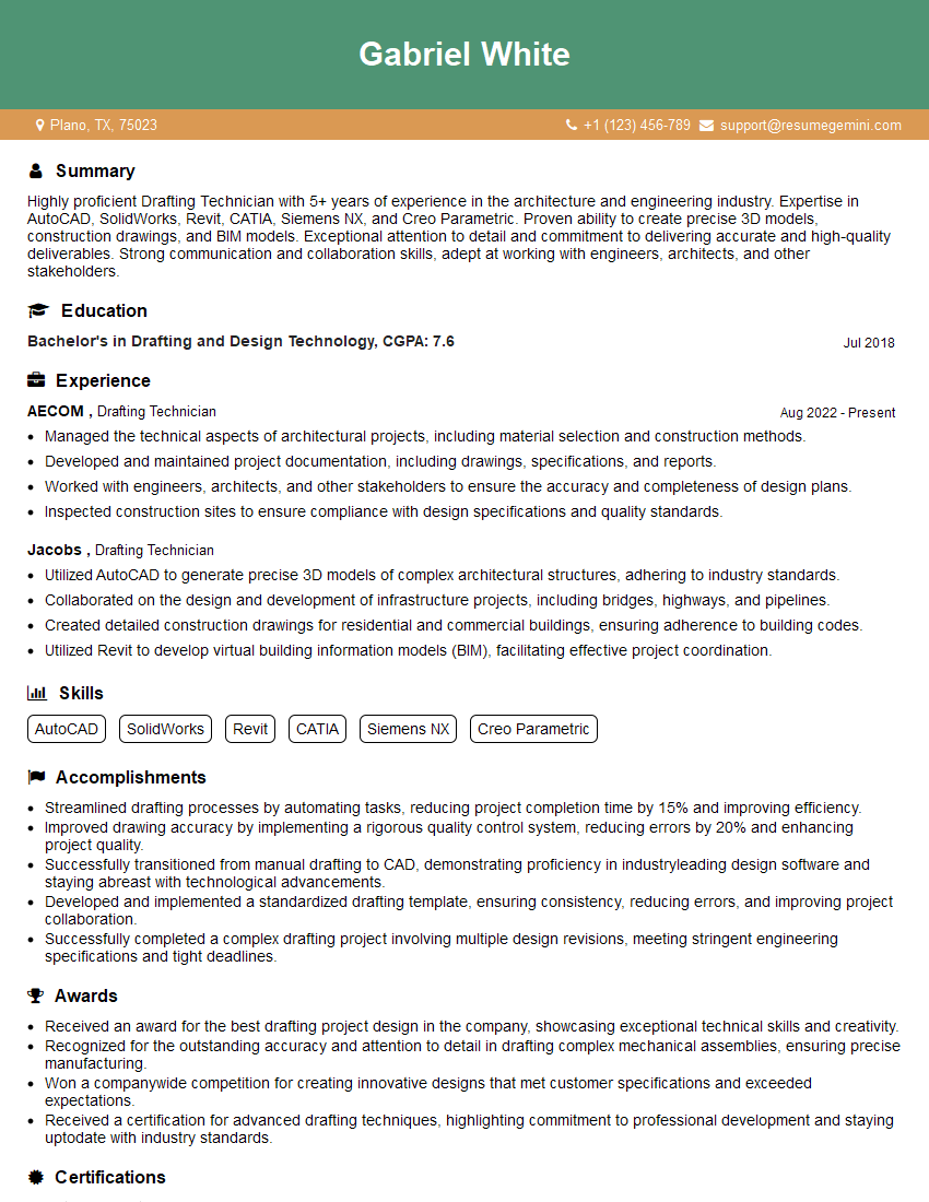
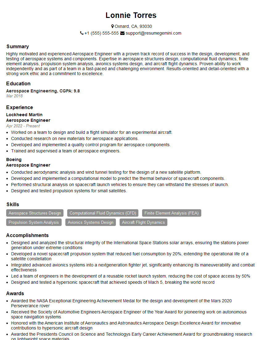
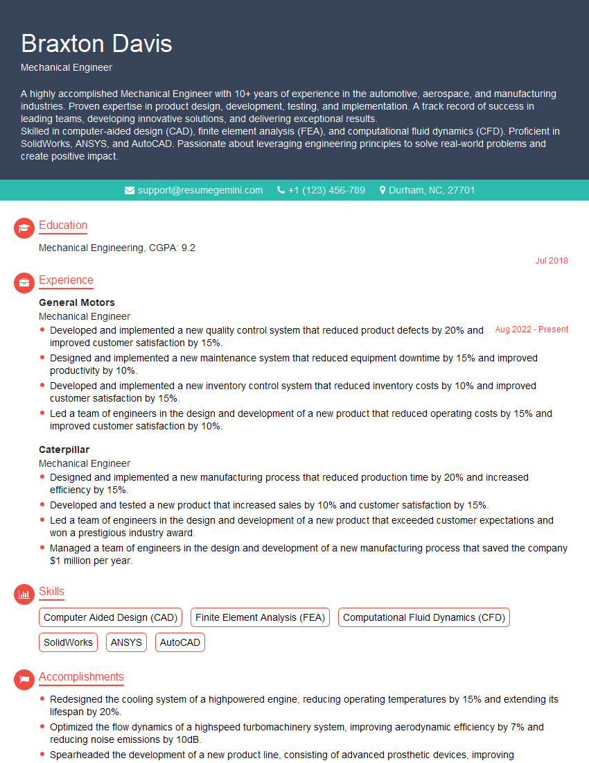
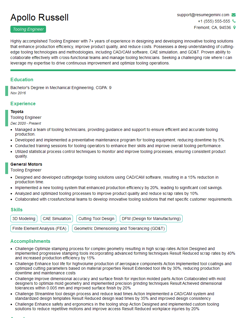
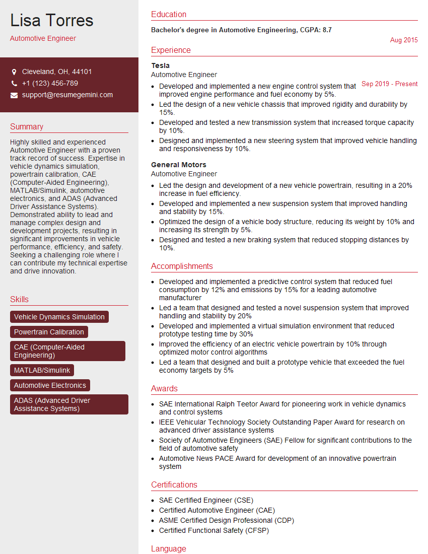
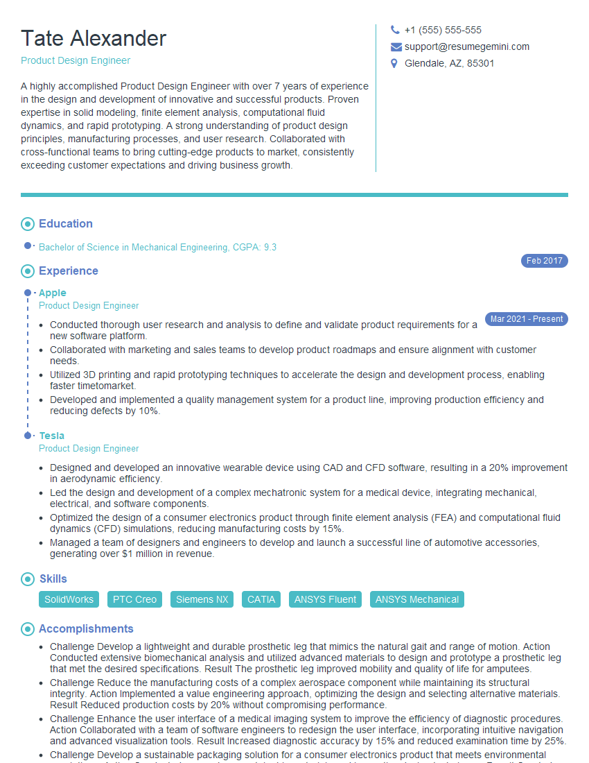
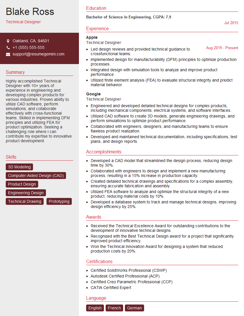
Mastering SolidWorks or CAD/CAM software is crucial for a successful and rewarding career in engineering and manufacturing. Proficiency in these tools opens doors to a wide range of exciting opportunities and allows you to contribute meaningfully to innovative projects. To maximize your job prospects, create an ATS-friendly resume that highlights your skills and experience effectively. ResumeGemini is a trusted resource that can help you build a professional and impactful resume tailored to the specific requirements of your target roles. Examples of resumes tailored to SolidWorks and CAD/CAM software positions are available to guide you through the process.
Explore more articles
Users Rating of Our Blogs
Share Your Experience
We value your feedback! Please rate our content and share your thoughts (optional).
What Readers Say About Our Blog
Hi, I’m Jay, we have a few potential clients that are interested in your services, thought you might be a good fit. I’d love to talk about the details, when do you have time to talk?
Best,
Jay
Founder | CEO

