Feeling uncertain about what to expect in your upcoming interview? We’ve got you covered! This blog highlights the most important Mechanical and Electrical Knowledge interview questions and provides actionable advice to help you stand out as the ideal candidate. Let’s pave the way for your success.
Questions Asked in Mechanical and Electrical Knowledge Interview
Q 1. Explain the difference between AC and DC electricity.
The fundamental difference between AC (Alternating Current) and DC (Direct Current) electricity lies in the direction of electron flow. In DC, electrons flow consistently in one direction, like a river flowing downstream. This is the type of electricity produced by batteries. In AC, the direction of electron flow periodically reverses, oscillating back and forth like a wave on the ocean. This is the type of electricity that powers our homes and most industries.
Think of it this way: DC is like a water slide – the water always moves in one direction. AC is like a seesaw – it goes back and forth.
This difference has significant implications for how electricity is generated, transmitted, and used. AC is more efficient for long-distance transmission because its voltage can be easily stepped up and down using transformers, minimizing energy loss. DC, on the other hand, is often preferred for applications requiring stable voltage, like powering electronic devices.
Q 2. Describe Ohm’s Law and its applications.
Ohm’s Law describes the relationship between voltage (V), current (I), and resistance (R) in an electrical circuit. It’s a fundamental principle in electrical engineering, stating that the current flowing through a conductor is directly proportional to the voltage across it and inversely proportional to its resistance.
Mathematically, it’s represented as: V = IR
Where:
- V is the voltage measured in volts (V)
- I is the current measured in amperes (A)
- R is the resistance measured in ohms (Ω)
Applications: Ohm’s Law is incredibly versatile. It’s used to:
- Calculate the current flowing through a circuit given the voltage and resistance.
- Determine the voltage required to drive a specific current through a given resistance.
- Calculate the resistance of a component given the voltage and current.
- Design circuits by selecting appropriate components to achieve desired current and voltage levels.
- Troubleshoot circuits by identifying faulty components based on measured voltage and current values.
For example, if a 12V battery is connected to a 6Ω resistor, the current flowing through the resistor can be calculated as: I = V/R = 12V / 6Ω = 2A
Q 3. What are the different types of motors and their applications?
Motors convert electrical energy into mechanical energy. There’s a wide variety, categorized based on their working principles and applications. Here are some key types:
- DC Motors: These use direct current to produce rotational motion. Subtypes include brushed DC motors (simple, inexpensive, but less efficient), brushless DC motors (more efficient, longer lifespan), and stepper motors (precise control of angular movement).
- AC Motors: These use alternating current. Common types include induction motors (robust, simple, widely used in industrial applications like fans and pumps) and synchronous motors (precise speed control, often used in clocks and timing devices).
- Servo Motors: These are precise, closed-loop motors that provide accurate position control. They’re often used in robotics and automation systems.
- Linear Motors: These convert electrical energy into linear motion, as opposed to rotational motion. They’re found in applications like high-speed trains and industrial positioning systems.
Applications are diverse and depend on the motor type. DC motors are suitable for applications requiring precise speed control, such as robotics. AC induction motors are preferred for their robustness and low cost in industrial applications like pumps and fans. Servo motors excel in precise positioning, while linear motors facilitate direct linear movement.
Q 4. Explain the principles of thermodynamics.
Thermodynamics deals with the relationships between heat, work, and energy. It’s governed by four fundamental laws:
- Zeroth Law: If two thermodynamic systems are each in thermal equilibrium with a third, then they are in thermal equilibrium with each other. This establishes the concept of temperature.
- First Law (Conservation of Energy): Energy cannot be created or destroyed, only transformed from one form to another. The total energy of an isolated system remains constant.
- Second Law (Entropy): The total entropy of an isolated system can only increase over time, or remain constant in ideal cases where the system is in a steady state or undergoing a reversible process. This essentially states that natural processes tend towards disorder.
- Third Law: The entropy of a perfect crystal at absolute zero temperature is zero. This sets a lower limit for entropy.
Real-world Applications: Thermodynamics underlies many engineering systems, including power plants (converting heat to mechanical energy), internal combustion engines (converting chemical energy to mechanical energy), refrigeration systems (transferring heat from a cold space to a warmer space), and many more. Understanding thermodynamics is crucial for optimizing energy efficiency and designing sustainable systems.
Q 5. How do you troubleshoot a faulty circuit?
Troubleshooting a faulty circuit involves a systematic approach. Here’s a step-by-step process:
- Safety First: Ensure the power is OFF before touching any components.
- Visual Inspection: Examine the circuit for any obvious problems like loose connections, burnt components, or physical damage.
- Check Power Supply: Verify that the power supply is providing the correct voltage.
- Measure Voltage: Use a multimeter to measure the voltage at various points in the circuit, comparing the readings to the expected values. This helps identify where the voltage drops or anomalies occur.
- Measure Current: Similarly, measure the current flowing through different parts of the circuit. This helps pinpoint components consuming excessive or insufficient current.
- Check Resistance: Measure the resistance of individual components to identify those that are open or shorted.
- Isolating Faulty Components: Using the voltage, current, and resistance measurements, progressively isolate the section or component causing the fault.
- Replace Faulty Components: Once the faulty component is identified, replace it with a new one.
- Test Circuit: After making repairs, retest the entire circuit to ensure it’s functioning correctly.
Example: If a light bulb doesn’t turn on, you might first check if the bulb is burned out. If it’s not, you’d measure the voltage at the socket. If no voltage is present, you’d trace the circuit back to the power supply to identify the problem in the wiring or the switch.
Q 6. Describe different types of sensors and their use in automation.
Sensors are devices that detect and respond to some type of input from the physical environment. They convert physical phenomena (light, temperature, pressure, etc.) into electrical signals that can be processed by a computer or control system. They are fundamental components in automation.
- Temperature Sensors: Thermocouples, RTDs (Resistance Temperature Detectors), and thermistors measure temperature variations.
- Pressure Sensors: Piezoresistive, capacitive, and strain gauge sensors detect pressure changes.
- Optical Sensors: Photodiodes, phototransistors, and CCDs (Charge-Coupled Devices) respond to light intensity.
- Proximity Sensors: Inductive, capacitive, and ultrasonic sensors detect the presence of nearby objects without physical contact.
- Flow Sensors: These measure the flow rate of liquids or gases.
- Position Sensors: Potentiometers, encoders, and Hall-effect sensors detect the position or movement of objects.
Use in Automation: Sensors play a vital role in automation by providing feedback to control systems. For example, a temperature sensor in a thermostat adjusts the heating/cooling system based on the measured temperature. Proximity sensors in robots prevent collisions. Flow sensors monitor liquid levels in industrial processes. In essence, sensors enable automated systems to react to real-world conditions and maintain desired operation.
Q 7. Explain the working principle of a hydraulic system.
Hydraulic systems use pressurized liquid to transmit power from one point to another. They operate based on Pascal’s principle, which states that pressure applied to a confined fluid is transmitted equally in all directions.
A typical hydraulic system consists of:
- Reservoir: Stores the hydraulic fluid.
- Pump: Pressurizes the fluid.
- Valves: Control the flow and direction of the fluid.
- Actuators: Convert hydraulic pressure into mechanical work (e.g., hydraulic cylinders or motors).
Working Principle: The pump pressurizes the hydraulic fluid, which is then directed by valves to the actuators. The pressure exerted on the actuator causes it to move, generating force or motion. The fluid then returns to the reservoir. This closed-loop system allows for precise control of force and movement.
Examples: Hydraulic systems are found in many applications, including construction equipment (e.g., excavators, bulldozers), aircraft control systems, and heavy machinery. Their high power-to-weight ratio and ability to generate significant force make them ideal for these applications.
Q 8. What are the different types of bearings and their applications?
Bearings are mechanical components that reduce friction between moving parts. Different types are chosen based on the specific application’s load, speed, and required precision.
- Rolling Element Bearings: These use balls or rollers to separate moving surfaces. They offer low friction and are suitable for high speeds. Examples include ball bearings (used in bicycles, motors), roller bearings (used in heavy machinery like conveyor belts), and tapered roller bearings (used in automotive wheel hubs).
- Journal Bearings (Sliding Bearings): These use a lubricant film to separate moving surfaces. They handle heavy radial loads but are generally slower than rolling element bearings. Examples include plain journal bearings in engine crankshafts and thrust bearings in turbines.
- Fluid Film Bearings: These use a pressurized fluid film (like oil or air) to separate the surfaces. They are used in high-speed applications where minimal friction is crucial, such as gas turbine engines and high-speed spindles.
- Magnetic Bearings: These use magnetic forces to levitate a rotor. They are found in very specialized applications requiring extremely precise positioning and high speeds, such as in some types of pumps and hard disk drives.
The choice of bearing depends heavily on factors such as load capacity, speed, operating temperature, required lifespan, and cost. For instance, a high-speed motor might use precision ball bearings, while a heavy-duty truck axle might utilize robust tapered roller bearings.
Q 9. Describe the different types of gears and their uses.
Gears are toothed wheels that transmit rotational motion and torque between shafts. Different types cater to various speed and torque ratios, and application demands.
- Spur Gears: These have straight teeth parallel to the shaft axis. Simple and efficient for parallel shafts, but can be noisy at high speeds. Used in many common machines, like clocks and simple gearboxes.
- Helical Gears: These have teeth angled along the shaft axis, providing smoother and quieter operation than spur gears. They can however transmit axial thrust. Used in automotive transmissions and power tools.
- Bevel Gears: These have teeth on conical surfaces and transmit power between intersecting shafts. Often found in differential gearboxes in cars and in some hand drills.
- Worm Gears: These consist of a worm (screw-like gear) and a worm wheel (gear with helical teeth). They offer high gear ratios and self-locking capabilities, meaning the output shaft won’t rotate when the input is stopped. Used in jacks, elevators, and conveyors.
- Rack and Pinion Gears: These convert rotary motion to linear motion. The rack is a linear gear, and the pinion is a circular gear meshing with it. Common in steering mechanisms and linear actuators.
The design of a gear system is critical. For instance, choosing between helical and spur gears depends on noise levels and speed requirements. A high torque application would likely benefit from a worm gear’s high gear ratio.
Q 10. Explain the concept of power factor correction.
Power factor correction improves the efficiency of electrical systems by reducing the reactive power. Inductive loads like motors and transformers draw reactive power, which doesn’t perform useful work but increases current flow and losses. A low power factor means more current is drawn than necessary to do the same amount of work, leading to higher electricity bills and greater stress on equipment.
Power factor correction involves adding capacitive reactance to the system to offset the inductive reactance. Capacitors store energy, releasing it during the part of the AC cycle when the inductive load is drawing current. This reduces the overall reactive power demand and thus improves the power factor towards unity (1).
Methods: Power factor correction can be achieved using individual capacitors connected to individual loads, or via larger capacitor banks for the entire system. The size of the capacitor bank is calculated based on the load’s reactive power demand and the desired power factor improvement.
Benefits: Increased efficiency, reduced electricity bills, reduced line losses, and improved equipment lifespan are all key benefits of implementing power factor correction. Imagine a factory with many motors: Power factor correction can significantly lower their electricity consumption without affecting production.
Q 11. What is the difference between a relay and a contactor?
Both relays and contactors are electromechanical switching devices, but they serve different purposes and have different capacities.
- Relay: A relay uses a small current to control a larger current. It acts as a switch, often used for control and protection functions. Relays are usually smaller and have lower current and voltage ratings than contactors. Think of a relay as an electrical switch controlled by a low-power signal. They’re used in control circuits, alarm systems, and overcurrent protection.
- Contactor: A contactor is a heavier-duty switch capable of carrying high currents. It’s primarily used for switching motors and other high-power loads. Contactors are typically larger, with higher current and voltage ratings, and designed to handle high inrush currents. They are the electrical equivalent of a large, powerful switch used to control large electrical machinery.
In essence, a relay acts as a control device for smaller circuits, while a contactor directly switches significant power to heavy loads. For instance, a motor control circuit might use a relay to control the contactor, ensuring the contactor only switches on when it’s safe and the motor is ready.
Q 12. Explain the concept of PLC programming.
PLC (Programmable Logic Controller) programming involves creating a program to control industrial machinery and processes. PLCs use ladder logic, a graphical programming language resembling electrical relay logic diagrams. This makes it easy to understand and implement control sequences.
Ladder Logic: It’s composed of ‘rungs’ representing logical statements. Each rung has inputs (switches, sensors) on the left and outputs (motors, lights) on the right. Programmers use logical operators (AND, OR, NOT) to create relationships between inputs and outputs, defining the system’s behavior under various conditions. For example, a motor might only turn on (output) when a pressure switch is closed (input) and a limit switch is open (input).
Example: (Simplified ladder logic) // Rung 1 Pressure Switch --[ ]-- Motor // Rung 2 Limit Switch --[ ]--[NOT]-- Motor
PLC Programming Steps: Typically involves creating the ladder logic program, uploading it to the PLC, testing the program with the real or simulated inputs and outputs, and troubleshooting any issues. PLCs are ubiquitous in industrial automation, controlling everything from assembly lines to chemical processes.
Q 13. Describe your experience with SCADA systems.
I have extensive experience with SCADA (Supervisory Control and Data Acquisition) systems, particularly in [mention specific applications or industries, e.g., water treatment plants, oil and gas pipelines]. My experience includes designing, implementing, and maintaining SCADA systems using [mention specific software packages, e.g., Wonderware, Siemens WinCC].
My responsibilities encompassed [mention specific tasks, e.g., configuring PLCs, designing HMI (Human-Machine Interface) screens, developing alarm management systems, integrating various field devices, and creating historical data archiving systems]. I’m familiar with various communication protocols used in SCADA, including [mention specific protocols, e.g., Modbus, Profibus, Ethernet/IP]. I have also been involved in troubleshooting and resolving issues in existing SCADA systems, optimizing their performance, and providing technical support to operations personnel. A notable project involved [briefly describe a significant project highlighting your skills and contributions].
My expertise extends to ensuring data security within SCADA environments, adhering to industry best practices and complying with relevant regulations.
Q 14. How do you perform a motor load test?
A motor load test determines the actual load a motor is carrying under operating conditions. It helps to assess the motor’s efficiency, identify potential problems, and ensures it’s appropriately sized for its application.
Methods: Several methods exist, ranging from simple measurements to more sophisticated techniques.
- Ammeter Method: This is a relatively simple method where the motor’s current draw is measured using an ammeter. Comparing the measured current with the motor’s nameplate rating indicates the load percentage. However, this method provides only an indirect measure and doesn’t account for power factor.
- Clamp Meter Method: Similar to the ammeter method but using a clamp meter to measure current without disconnecting any wires. Convenient and less disruptive, but again, it only gives an indirect measure of load.
- Power Meter Method: A power meter measures both voltage and current, providing a more accurate calculation of power consumption. This helps determine the motor’s actual load (kW) and improves accuracy compared to current-only measurements.
- Load Cell Method: For mechanical load determination, a load cell placed on the output shaft measures the actual torque being applied by the motor. This method is most accurate but typically requires specialized equipment.
Steps (general): The specific steps depend on the chosen method. However, generally, you’ll need to safely isolate the motor, connect the measurement equipment, run the motor under typical operating conditions, record measurements, and then analyze the data to determine the load. Safety precautions are paramount when testing industrial motors.
Example: In a pump application, a power meter might be used to measure the pump’s electrical input power. Knowing the pump’s efficiency (from its specifications), the actual hydraulic power output can be calculated to determine the load it’s currently handling.
Q 15. Explain the principles of fluid mechanics.
Fluid mechanics is the branch of physics that studies how fluids (liquids and gases) behave under various conditions. It’s governed by fundamental principles like conservation of mass, momentum, and energy. These principles are expressed through equations that describe fluid motion, pressure, and forces.
Key Principles:
- Conservation of Mass (Continuity Equation): States that the mass flow rate into a system equals the mass flow rate out. Imagine a pipe – the amount of water entering one end must equal the amount leaving the other, assuming no leaks or accumulation.
- Conservation of Momentum (Navier-Stokes Equations): These complex equations describe the forces acting on a fluid element, including pressure forces, viscous forces (resistance to flow), and inertial forces (resistance to changes in motion). They’re fundamental to understanding fluid flow in complex geometries.
- Conservation of Energy (Bernoulli’s Equation): This simplified equation (applicable to inviscid, incompressible flows) relates pressure, velocity, and elevation in a flowing fluid. Think of an airplane wing – the faster air flows over the curved upper surface, the lower the pressure, creating lift.
Practical Applications: Fluid mechanics is crucial in numerous fields, including aerospace engineering (designing aircraft wings), civil engineering (designing efficient water distribution systems), and mechanical engineering (designing pumps, turbines, and pipelines).
Career Expert Tips:
- Ace those interviews! Prepare effectively by reviewing the Top 50 Most Common Interview Questions on ResumeGemini.
- Navigate your job search with confidence! Explore a wide range of Career Tips on ResumeGemini. Learn about common challenges and recommendations to overcome them.
- Craft the perfect resume! Master the Art of Resume Writing with ResumeGemini’s guide. Showcase your unique qualifications and achievements effectively.
- Don’t miss out on holiday savings! Build your dream resume with ResumeGemini’s ATS optimized templates.
Q 16. What are the different types of welding processes?
Welding is a fabrication process that joins materials, usually metals or thermoplastics, by causing coalescence. Different welding processes employ various methods to achieve this fusion.
Types of Welding Processes:
- Arc Welding (SMAW, GMAW, GTAW): Uses an electric arc to melt the base material and filler material. SMAW (Shielded Metal Arc Welding) uses a coated electrode; GMAW (Gas Metal Arc Welding) uses a continuously fed wire; and GTAW (Gas Tungsten Arc Welding) uses a non-consumable tungsten electrode.
- Resistance Welding (Spot Welding, Seam Welding): Uses electrical resistance to heat and join materials at the point of contact. Commonly used in the automotive industry for joining sheet metal.
- Gas Welding (Oxy-fuel Welding): Uses a flame produced by burning oxygen and fuel gas (acetylene) to melt the base material and filler material. This is often used for smaller projects or when precise control is needed.
- Friction Welding: Uses frictional heat generated by rotating one part against another to create the weld. This method is suitable for joining dissimilar metals.
- Laser Welding: Employs a high-powered laser beam to melt the base material and create a weld. Offers very precise welds and is used in applications where high quality and repeatability are vital.
Choosing the right process: The selection of a welding process depends on factors like the materials being joined, the required weld quality, the production volume, and cost considerations.
Q 17. Describe your experience with CAD software (e.g., AutoCAD, SolidWorks).
I have extensive experience with several CAD software packages, most notably AutoCAD and SolidWorks. My proficiency includes 2D drafting and 3D modeling, performing finite element analysis (FEA) simulations and generating manufacturing drawings.
AutoCAD: I’ve used AutoCAD extensively for creating detailed 2D drawings for manufacturing, including parts, assemblies, and building plans. I’m proficient in using various commands, layers, and annotations to produce clear, accurate technical drawings.
SolidWorks: SolidWorks has been instrumental in creating complex 3D models, performing simulations, and generating manufacturing documentation. I’ve used SolidWorks to design and analyze mechanical components, assemblies, and entire systems, utilizing its features for parametric modeling, simulations (e.g., stress analysis, flow simulation), and rendering to improve visualization. I’m comfortable with creating detailed assembly drawings, bill of materials (BOMs), and other manufacturing-related documents.
Example: In a previous role, I used SolidWorks to design a new component for a high-speed centrifuge. I leveraged the software’s simulation capabilities to optimize the design for stress and vibration, ensuring its reliability under high-speed operation.
Q 18. How do you design for manufacturability?
Designing for manufacturability (DFM) is a critical aspect of product development, ensuring that a design is cost-effective and efficient to produce. It involves considering the manufacturing processes from the outset of the design process.
Key Considerations in DFM:
- Material Selection: Choosing materials that are readily available, easy to process, and cost-effective.
- Simplification of Geometry: Reducing the number of parts and simplifying shapes to minimize machining time and costs.
- Feature Tolerance: Defining realistic tolerances to avoid tight tolerances that increase manufacturing costs and reduce yield.
- Assembly Considerations: Designing parts for easy assembly to reduce labor costs and improve production efficiency (e.g., using snap fits or press fits).
- Manufacturing Process Selection: Choosing appropriate manufacturing processes like casting, machining, or additive manufacturing based on design requirements and cost considerations.
Example: Instead of designing a complex part requiring multiple machining operations, DFM might suggest using a simpler design that can be easily cast or produced via additive manufacturing, reducing the overall manufacturing costs and lead time.
Q 19. Explain the concept of stress and strain.
Stress and strain are fundamental concepts in materials science and mechanics. They describe how a material responds to an applied force.
Stress: Stress (σ) is defined as the internal force (F) acting on a material per unit area (A): σ = F/A. It’s a measure of the internal forces within a material caused by external loads. Units are typically Pascals (Pa) or pounds per square inch (psi).
Strain: Strain (ε) is the deformation of a material caused by an applied stress. It’s defined as the change in length (ΔL) divided by the original length (L): ε = ΔL/L. Strain is dimensionless.
Relationship between Stress and Strain: The relationship between stress and strain is described by the material’s constitutive law, often a stress-strain curve. This curve shows how the material behaves under different loading conditions. For many materials, at low stress levels, the relationship is linear, and the slope of the curve is the Young’s modulus (elastic modulus), representing the material’s stiffness.
Example: Imagine stretching a rubber band. The force you apply creates stress within the rubber band. The increase in the rubber band’s length is the strain. The relationship between the force and the elongation describes the rubber band’s material properties.
Q 20. What are different types of material testing methods?
Material testing methods are used to determine the mechanical properties of materials. Different methods are used depending on the desired information and the type of material.
Types of Material Testing Methods:
- Tensile Testing: Measures the material’s strength and ductility by subjecting a specimen to a uniaxial tensile force. Provides parameters like yield strength, ultimate tensile strength, and elongation.
- Compression Testing: Measures the material’s response to compressive forces. Useful for materials like concrete or ceramics.
- Shear Testing: Measures the material’s resistance to shear forces. Used to determine shear strength and modulus.
- Hardness Testing: Determines the material’s resistance to indentation. Common methods include Brinell, Rockwell, and Vickers hardness tests.
- Fatigue Testing: Determines the material’s endurance limit or fatigue strength by subjecting it to cyclic loading.
- Impact Testing: Measures the material’s ability to absorb energy from a sudden impact. Charpy and Izod impact tests are common examples.
- Creep Testing: Measures the material’s deformation under sustained stress at elevated temperatures.
Choosing the right test: The selection of a material testing method depends on factors like the material type, the application requirements, and the properties of interest.
Q 21. How do you calculate the efficiency of a motor?
The efficiency of a motor is the ratio of the useful mechanical power output to the electrical power input. It represents how effectively the motor converts electrical energy into mechanical work.
Calculating Motor Efficiency:
Efficiency (η) = (Mechanical Power Output / Electrical Power Input) x 100%
Mechanical Power Output: This can be calculated using the following formula: Pout = (Torque x Angular Speed) / 9.549 (where Torque is in lb-ft, and angular speed is in rpm). For SI units, use: Pout = Torque x Angular Speed (Torque in Nm and angular speed in rad/s).
Electrical Power Input: This can be measured directly using a power meter or calculated from the motor’s voltage (V) and current (I): Pin = V x I x power factor. The power factor accounts for the phase difference between voltage and current in AC motors.
Example: Suppose a motor has an electrical power input of 10 kW and a mechanical power output of 8 kW. The efficiency would be: (8 kW / 10 kW) x 100% = 80%.
Factors affecting motor efficiency: Motor efficiency can be affected by several factors, including motor design, load, temperature, and the condition of the motor’s bearings and windings. Higher efficiency motors are generally more expensive but result in energy savings over their lifetime.
Q 22. Explain your understanding of safety regulations in electrical work.
Safety in electrical work is paramount and hinges on a thorough understanding of regulations and best practices. It’s not just about avoiding shocks; it’s about preventing fires, explosions, and injuries. My understanding encompasses several key areas:
- Lockout/Tagout (LOTO): This crucial procedure ensures that electrical equipment is de-energized and cannot be accidentally re-energized during maintenance or repair. I’ve extensively used LOTO procedures in various industrial settings, always verifying the de-energized state using appropriate testing equipment before commencing work.
- Personal Protective Equipment (PPE): The appropriate PPE, including insulated gloves, safety glasses, and arc flash suits (depending on the voltage), is essential. I always choose the correct PPE for the task and ensure it’s in good condition before starting any electrical work. For example, working with high-voltage systems necessitates the use of arc flash suits to mitigate the risk of severe burns.
- Electrical Codes and Standards: Familiarity with codes like NEC (National Electrical Code) and OSHA regulations is critical. I consistently refer to these codes to ensure compliance and implement safe practices. This includes understanding grounding, bonding, and proper wiring techniques to prevent short circuits and other hazards.
- Electrical Safety Training and Certifications: I possess necessary certifications demonstrating my competence and adherence to safety standards. Regular refresher training keeps my knowledge updated on the latest safety procedures and technologies.
Ignoring safety regulations can have catastrophic consequences, ranging from minor injuries to fatalities. A proactive approach, adhering strictly to procedures, and prioritizing safety above all else are my guiding principles in electrical work.
Q 23. Describe your experience with troubleshooting mechanical systems.
My experience with troubleshooting mechanical systems involves a systematic approach that blends practical skills with analytical thinking. I’ve successfully tackled a wide range of issues, from simple component failures to complex system malfunctions.
For example, I once worked on a conveyor system experiencing frequent stoppages. My troubleshooting steps included:
- Initial Observation: I meticulously observed the system’s operation, noting any unusual sounds, vibrations, or behaviors. This revealed that the system would stall at a specific point along the conveyor belt.
- Data Collection: I checked motor currents, belt tension, and examined the alignment of the system components. This stage frequently involves using measurement tools such as multimeters, vibration sensors, and laser alignment tools.
- Component Testing: I systematically tested individual components like motors, bearings, and sensors to isolate the faulty part. This often includes replacing suspect components one at a time and observing the effects.
- Root Cause Analysis: Once the faulty component was identified (a worn bearing in this instance), I delved deeper to determine the root cause of the failure. Was it due to insufficient lubrication, excessive load, or improper installation? This analysis ensures that the same problem doesn’t reoccur.
- Repair and Prevention: The worn bearing was replaced, and I implemented preventative measures – better lubrication schedules and improved belt tension monitoring – to prevent future failures.
This systematic approach, coupled with experience in various mechanical systems, has allowed me to efficiently diagnose and resolve mechanical problems effectively.
Q 24. How do you perform root cause analysis for equipment failure?
Root cause analysis (RCA) is crucial for preventing equipment failures and improving system reliability. My approach follows a structured methodology, often employing techniques like the ‘5 Whys’ and fishbone diagrams.
The process generally begins with clearly defining the problem. Then:
- Data Gathering: I collect data from various sources, including maintenance logs, operator reports, and sensor readings. This helps to build a comprehensive picture of the failure.
- Identify Potential Causes: Using techniques like brainstorming and the fishbone diagram (Ishikawa diagram), I identify potential contributing factors. These could be related to design flaws, manufacturing defects, operating conditions, or maintenance practices.
- Verify Causes: I systematically investigate each potential cause, employing various analytical tools and testing methods to determine the likelihood of each contributing factor.
- Identify Root Cause: By eliminating less likely causes, I progressively narrow down to the root cause of the failure. The ‘5 Whys’ technique is very effective here – repeatedly asking ‘why’ helps to drill down to the fundamental problem.
- Develop Corrective Actions: Based on the identified root cause, I develop and implement corrective actions that address the issue directly and prevent recurrence. These could involve design modifications, improved maintenance procedures, or operator training.
For instance, if a pump repeatedly fails due to bearing wear, simply replacing the bearings isn’t sufficient. An RCA might reveal that excessive vibration is the root cause, potentially stemming from misalignment of the pump shaft or an unbalanced impeller. The corrective action would then be to address the misalignment or imbalance.
Q 25. Explain your experience with project management techniques.
My project management experience spans various methodologies, including Agile and Waterfall. I am proficient in managing projects across the entire lifecycle, from initiation and planning to execution, monitoring, and closure.
Key techniques I employ include:
- Scope Definition: Clearly defining the project goals, deliverables, and constraints is the foundation of successful project management. I use tools like Work Breakdown Structures (WBS) to decompose complex projects into manageable tasks.
- Scheduling and Resource Allocation: I utilize Gantt charts and critical path analysis to create realistic project schedules and allocate resources effectively. This involves considering dependencies between tasks and potential risks to the timeline.
- Risk Management: Proactive risk identification and mitigation are crucial. I create risk registers and develop contingency plans to address potential problems before they impact the project.
- Communication and Collaboration: Maintaining clear and consistent communication with stakeholders is essential. Regular meetings, progress reports, and proactive issue management ensure transparency and collaboration.
- Quality Control: Implementing quality checks throughout the project lifecycle ensures that deliverables meet the required standards. This might involve regular inspections, testing, and reviews.
I’ve successfully managed numerous projects within budget and on schedule, consistently delivering high-quality results. My experience encompasses projects of varying scales and complexity, in both mechanical and electrical domains.
Q 26. Describe your experience with different types of pumps.
My experience encompasses a variety of pump types, each suited for specific applications. Here are a few examples:
- Centrifugal Pumps: These are widely used for moving liquids using centrifugal force. I’ve worked with various designs, including radial and axial flow pumps, understanding their performance characteristics and limitations. For instance, I once optimized a centrifugal pump system by adjusting the impeller diameter to improve efficiency for a specific application.
- Positive Displacement Pumps: These pumps move a fixed volume of liquid with each stroke. I have experience with various types, including piston pumps, gear pumps, and diaphragm pumps. Their ability to handle high viscosity fluids is a key advantage, and I’ve used them in applications requiring precise fluid delivery.
- Rotary Pumps: These pumps use rotating components to move fluids. I’m familiar with screw pumps and vane pumps, understanding their suitability for specific viscosity ranges and applications.
- Submersible Pumps: These pumps are immersed in the fluid being pumped, often used for well applications or in sumps. I’ve worked with these pumps, understanding their unique challenges regarding sealing and motor cooling.
Selecting the appropriate pump type requires considering factors like flow rate, head pressure, viscosity, fluid characteristics, and operational conditions. My knowledge and experience enable me to make informed decisions for various applications.
Q 27. What is your experience with industrial control systems?
My experience with industrial control systems (ICS) is substantial, encompassing both hardware and software aspects. I understand the various components involved, including Programmable Logic Controllers (PLCs), Human-Machine Interfaces (HMIs), supervisory control and data acquisition (SCADA) systems, and field instrumentation.
I’ve worked on projects involving:
- PLC Programming: I’m proficient in programming PLCs using various languages like Ladder Logic, Function Block Diagrams (FBD), and Structured Text. This includes developing programs for controlling industrial machinery, automating processes, and managing data acquisition.
- HMI Design and Configuration: I have experience designing user-friendly HMIs that provide operators with a clear view of the system’s status and provide intuitive controls. This includes creating alarm management systems and visualizing process data effectively.
- SCADA System Integration: I’ve worked on integrating various components into SCADA systems to monitor and control geographically distributed assets. This includes configuring communication networks and ensuring seamless data exchange.
- Troubleshooting and Maintenance: I’ve successfully diagnosed and resolved issues in ICS, often involving tracing signals, debugging code, and analyzing data logs. This requires understanding both hardware and software components, and strong analytical skills.
My understanding of ICS security is also crucial. I am aware of the vulnerabilities of industrial networks and the importance of implementing appropriate security measures to protect against cyber threats.
Q 28. Explain your understanding of different types of control valves.
Control valves are essential components in industrial processes, regulating the flow of fluids or gases. I’m familiar with various types, each with its own characteristics and applications.
- Globe Valves: These are widely used and offer good controllability. They are suitable for a wide range of applications but can experience higher pressure drops than some other valve types.
- Ball Valves: These offer quick on/off control but generally provide less precise flow regulation than globe valves. They are often used for isolation purposes.
- Butterfly Valves: These are compact and relatively inexpensive but offer less precise flow control than globe valves, especially at lower flow rates. They are frequently used in larger diameter pipelines.
- Diaphragm Valves: These valves are often used in applications requiring leak-tight sealing. The diaphragm isolates the valve mechanism from the fluid, ideal for corrosive or abrasive fluids.
- Pinch Valves: These valves regulate flow by squeezing a flexible tube. They are well suited for slurries and materials with high particulate content.
The choice of control valve depends on many factors, such as the fluid properties, flow rate, pressure, required accuracy, and cost considerations. Understanding these factors is crucial for selecting the most suitable valve for a given application.
Key Topics to Learn for Mechanical and Electrical Knowledge Interview
- Mechanical Systems: Understanding fundamental principles like mechanics of materials, stress-strain analysis, thermodynamics, fluid mechanics, and machine design. Consider practical applications in areas such as HVAC systems, manufacturing processes, and robotics.
- Electrical Systems: Mastering core concepts including circuits, electromagnetism, power systems, control systems, and instrumentation. Explore practical applications in areas like power generation, distribution, automation, and electrical safety.
- Thermodynamics and Heat Transfer: Grasping the principles of thermodynamics, including energy conversion, heat transfer mechanisms (conduction, convection, radiation), and their applications in various engineering systems.
- Control Systems: Understanding feedback control loops, PID controllers, and their application in automation and process control. Be prepared to discuss practical examples and troubleshooting scenarios.
- Problem-Solving and Analytical Skills: Practice approaching technical problems methodically, utilizing problem-solving frameworks and demonstrating your ability to analyze complex systems and propose solutions.
- CAD/CAM Software: Familiarity with industry-standard CAD and CAM software is highly beneficial. Be ready to discuss your experience and proficiency level.
- Safety Regulations and Standards: Demonstrate awareness of relevant safety regulations and industry standards pertaining to both mechanical and electrical systems.
- Troubleshooting and Maintenance: Prepare to discuss your approach to troubleshooting common issues in mechanical and electrical systems and preventative maintenance strategies.
Next Steps
Mastering Mechanical and Electrical Knowledge is crucial for career advancement in numerous high-demand fields. A strong foundation in these areas opens doors to exciting opportunities and higher earning potential. To maximize your job prospects, invest time in crafting a compelling and ATS-friendly resume that effectively highlights your skills and experience. ResumeGemini is a trusted resource to help you build a professional resume that stands out. They offer examples of resumes tailored to Mechanical and Electrical Knowledge backgrounds to help guide you. Take advantage of these resources to present yourself in the best possible light and land your dream job!

Automation Engineer Resume Sample

Test Engineer Resume Sample
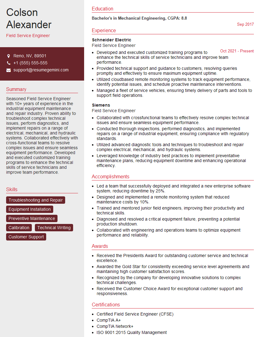
Field Service Engineer Resume Sample

Maintenance Engineer Resume Sample

Electronics Engineer Resume Sample

Electrical Engineer Resume Sample
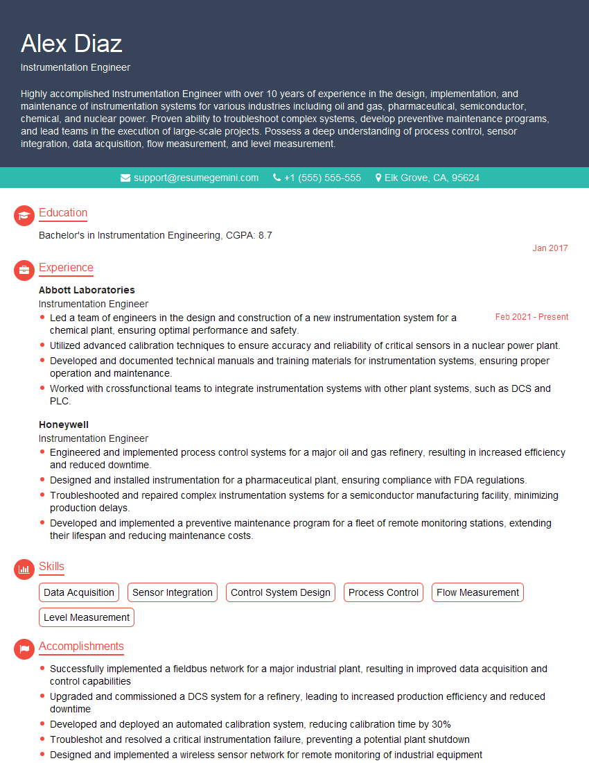
Instrumentation Engineer Resume Sample
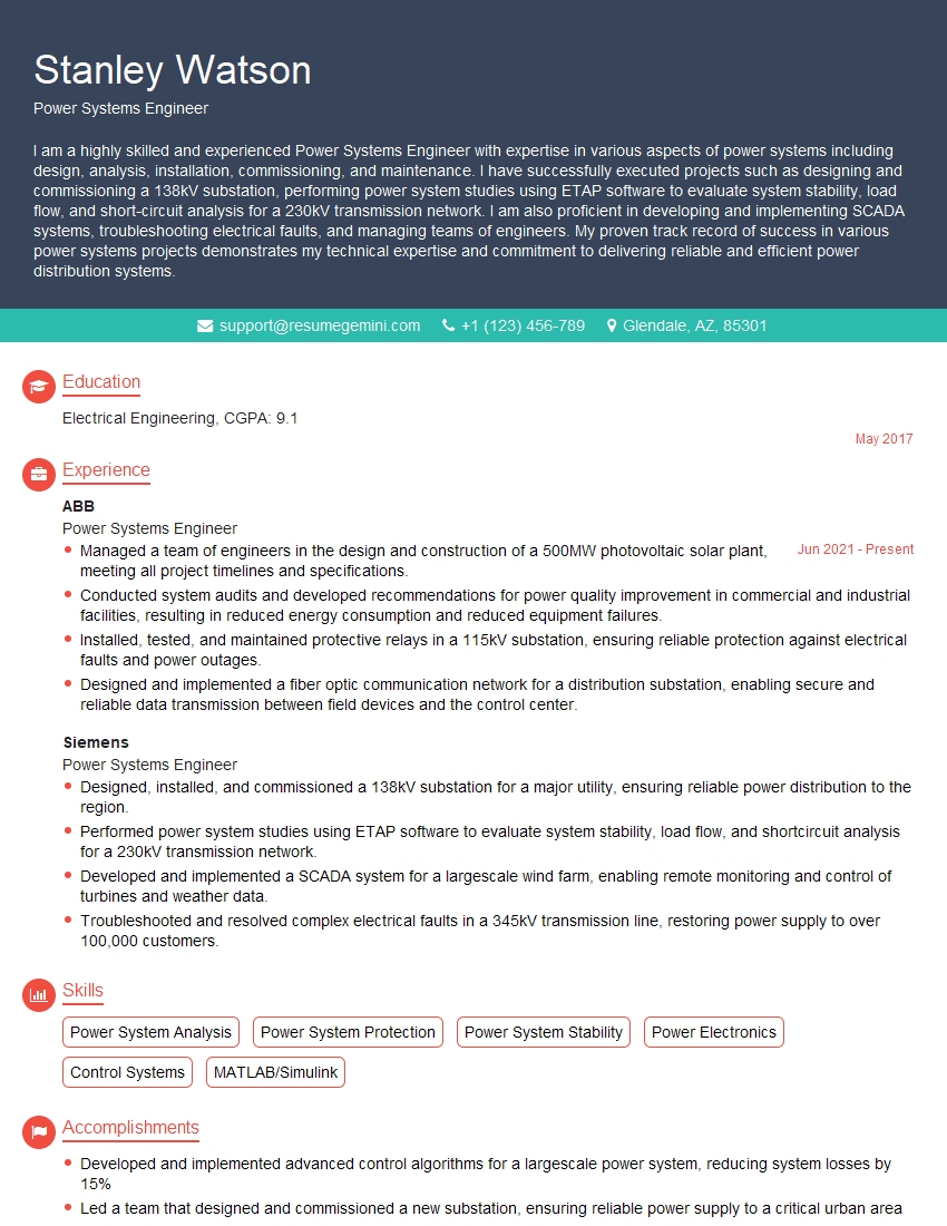
Power Systems Engineer Resume Sample

Manufacturing Engineer Resume Sample
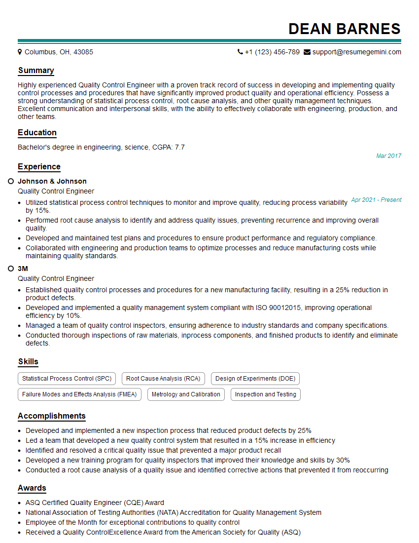
Quality Control Engineer Resume Sample
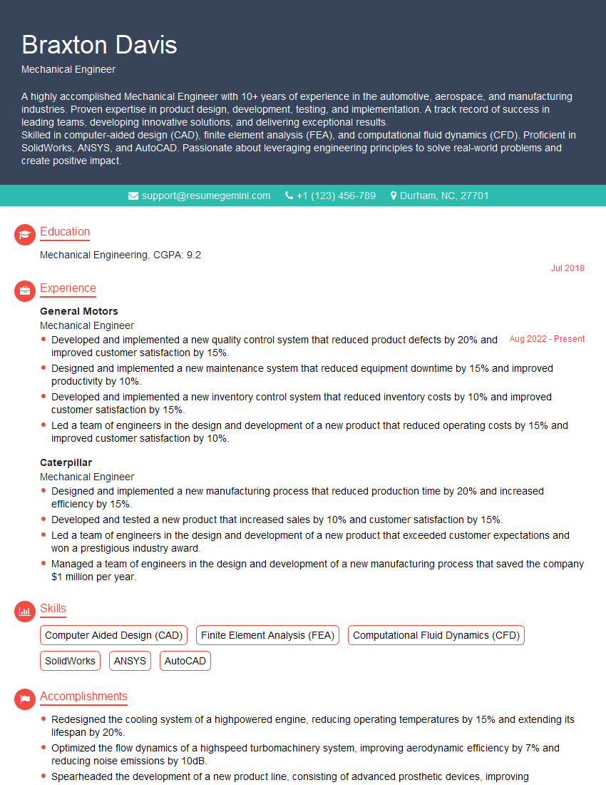
Mechanical Engineer Resume Sample

Control Systems Engineer Resume Sample

Mechatronics Engineer Resume Sample
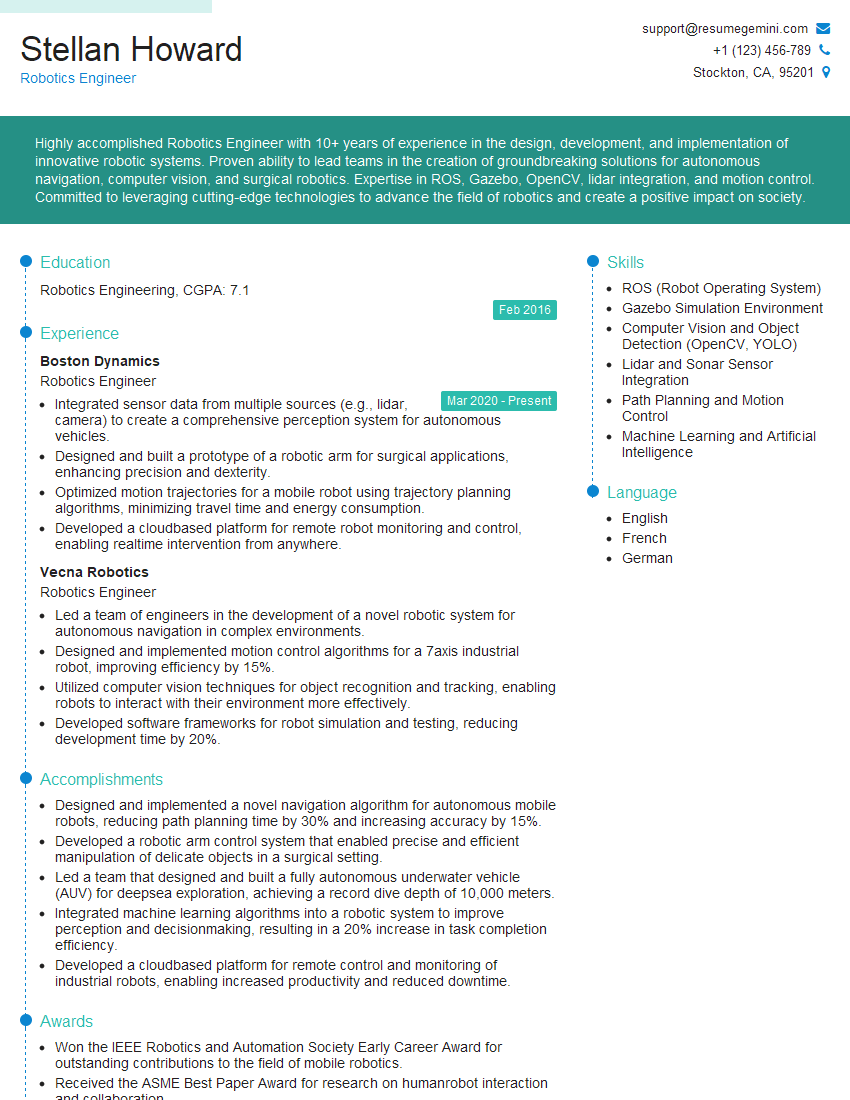
Robotics Engineer Resume Sample

Electrical Technician Resume Sample

Mechanical Technician Resume Sample
- Automation Engineer
- Test Engineer
- Field Service Engineer
- Maintenance Engineer
- Electronics Engineer
- Electrical Engineer
- Instrumentation Engineer
- Power Systems Engineer
- Manufacturing Engineer
- Quality Control Engineer
- Mechanical Engineer
- Control Systems Engineer
- Mechatronics Engineer
- Robotics Engineer
- Electrical Technician
- Mechanical Technician
Explore more articles
Users Rating of Our Blogs
Share Your Experience
We value your feedback! Please rate our content and share your thoughts (optional).
What Readers Say About Our Blog
Really detailed insights and content, thank you for writing this detailed article.
IT gave me an insight and words to use and be able to think of examples